
Table of contents: Automatic transmission "A5S 440Z" ↓ Automatic transmission "A5S390R" ↓
- Home
- BMW X5
- E53
- Transmission
- Automatic gearbox
- Replacing the speed sensors
Replacing the speed sensors (BMW X5 E53)
Automatic transmission "A5S 440Z"
The A5S 440Z automatic transmission has two speed sensors - output shaft and turbine. Before replacing the speed sensors, it is necessary to remove the automatic transmission oil pan. The output shaft speed sensor of the automatic transmission must be replaced in the following order.
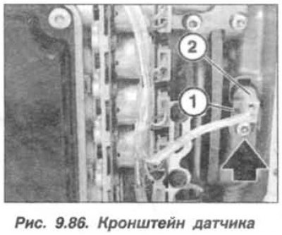
Unscrew the screw (arrow), remove the bracket (1, Fig. 9.86) and remove the sensor (2) from the automatic transmission housing. Disconnect the cable harness from the sensor.
When installing the automatic transmission input shaft speed sensor, tighten the screw (M5) for fastening its bracket to a torque of 5.0 N·m (0.5 kgf·m).
The replacement of the automatic transmission turbine speed sensor must be carried out in the following order.
Unscrew the screw (arrow), remove the bracket (1, Fig. 9.87) and remove the sensor (2) from the automatic transmission housing. Disconnect the cable harness from the sensor.
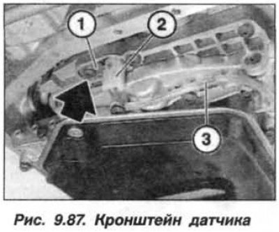
When installing the automatic transmission turbine speed sensor, secure the cable harness with a holder, tighten the screw (M5) securing the sensor bracket to a torque of 5.0 N·m (0.5 kgf·m).
The replacement of the automatic transmission turbine speed sensor must be carried out in the following order.
Unscrew the screw (arrow), remove the bracket (1, Fig. 9.87) and remove the sensor (2) from the automatic transmission housing. Disconnect the cable harness from the sensor.
When installing the automatic transmission turbine speed sensor, secure the cable harness with a holder, tighten the screw (M5) securing the sensor bracket to a torque of 5.0 N·m (0.5 kgf·m).
Automatic transmission "A5S390R"
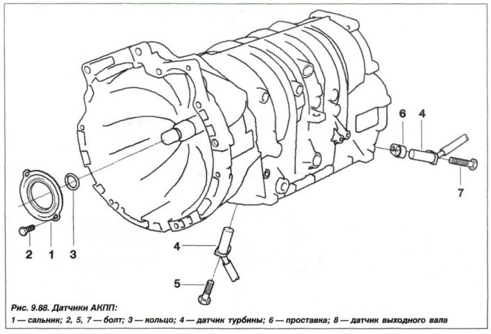
The structural arrangement of sensors on the crankcase of the automatic transmission "A5S390R" is shown in Figure 9.88.
The A5S 390R automatic transmission has two speed sensors - output shaft and turbine. Before replacing the speed sensors, it is necessary to remove the automatic transmission oil pan.
The replacement of the automatic transmission output shaft speed sensor must be carried out in the following order: Remove the automatic transmission oil pan and disconnect the shim (1, Fig. 9.89). Loosen the bolt (2), remove the bracket and remove the output shaft sensor (3) from the automatic transmission housing.
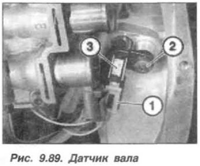
When installing the automatic transmission output shaft speed sensor, tighten the screw (M5) for fastening its bracket to a torque of 5.0 N·m (0.5 kgf·m). Upon completion of the work, check the oil level in the automatic transmission and, if necessary, restore it.
Read information from the fault memory of the ECU-KSUD and the EGS system. Check the fault messages entered into the memory. Eliminate faults and erase information from the memory.
The replacement of the automatic transmission turbine speed sensor must be carried out in the following order: Remove the automatic transmission oil pan and disconnect the SS (1, Fig. 9.90) from the turbine speed sensor. Unscrew the screw (2) securing the bracket and remove the sensor (3) from the automatic transmission housing.
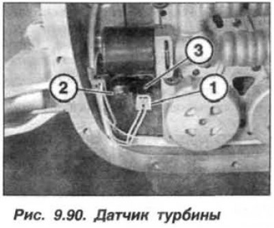
When installing the automatic transmission turbine speed sensor, secure the sensor bracket with a screw (M5), tightening it to a torque of 5.0 N·m (0.5 kgf·m). Upon completion of the work, check the oil level in the automatic transmission and, if necessary, restore it.
Read information from the ECU-KSUD fault memory. Check the fault messages entered into the memory and eliminate them. Erase information from the memory.
This article is available at russian, bulgarian, belarusian, ukrainian, serbian, croatian, romanian, polish, slovak, hungarian
Article verified: Zhuravleva Isolda
Share information:
Previous articles
БМВ E53: Automatic gearbox
Next articles
Similar articles on other types of BMW cars:
Checking the level and replacing the oil in the automatic transmission BMW 3 Series E21 (1975-1983)
Checking and replacing ignition sensors (Motronic system) BMW 5 Series E28 (1981-1988)
Replacing the coolant BMW 5 Series E12 (1972-1981)
Replacing the sensors of the engine management system BMW 7 Series E38 (1994-2001)
Replacing the oil filter (center bolt design) BMW 7 Series E32 (1986-1994)
Replacing the intake camshaft BMW X3 E83 (2003-2010)
Link in different formats to this page
Visitor comments
No comments yet
- General information
- Manual
- Maintenance
- M54 petrol engine
- Engine repair
- Lubrication system
- Cooling system
- Supply system
- Injection system
- Exhaust system
- Engine electrics
- M62 petrol engine
- Engine repair
- Lubrication system
- Cooling system
- Supply system
- Exhaust system
- Engine electrics
- N62 petrol engine
- Engine repair
- Cooling and lubrication system
- Power and exhaust system
- Engine electrics
- Diesel engine M57
- Engine repair
- Lubrication system
- Cooling system
- Power and exhaust system
- Engine electrics
- Turbocharging system
- Transmission
- Clutch
- Mechanical gearbox
- Automatic gearbox
- Transfer case and cardan
- Chassis
- Brake system
- Steering
- Front suspension
- Rear suspension
- Wheels and tires
- Body
- Exterior
- Interior
- Doors and windows
- Repair and maintenance
- Heater and air conditioner
- Electrical equipment
- Equipment and devices
- Levers and switches
- Electrical circuits