
Warning! It is prohibited to disassemble the gear shift bracket.
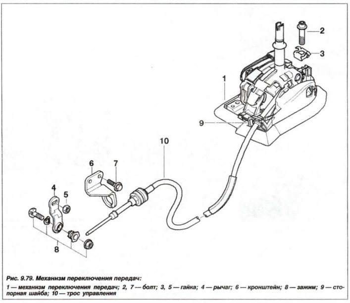
The design of the gear shift mechanism (GSM) is shown in Figure 9.79.
The gearshift mechanism bracket must be removed in the following order. Set the automatic transmission control selector to position "P" and, if necessary, remove the lower automatic transmission casing.
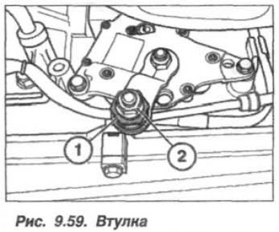
Holding the clamp (1, see Fig. 9.59), loosen the nut (2).
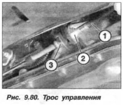
Holding the rope (1, Fig. 9.80) from turning by the hex head (2), unscrew the nut (3). On the automatic transmission "GA6HP26Z" use a screwdriver to remove the downward control cable bracket. Remove the cable (1) from the bracket.
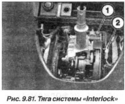
Remove the small items drawer if it is in the way and unscrew the screw (1, Fig. 9.81) "Interlock" system rods. Remove the wire harness (2) from the holders and disconnect it. Disconnect the automatic transmission control system rod (3) and remove the wire harness from the holders. Unscrew the mounting bolts, hook and slightly lift the gearshift mechanism bracket (4). Disconnect the "Interlock" system rod and remove the gearshift mechanism bracket together with the rod.
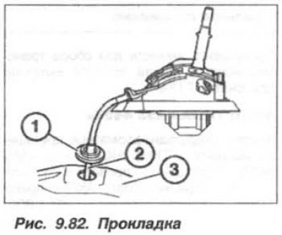
The gear shift bracket should be installed in reverse order, and the rubber gasket must be inserted (1, Fig. 9.82) gear shift rods (2) into the tunnel (3) of the automatic transmission.
Secure the wiring harness with holders/bandages. Tighten the gearshift mechanism bracket mounting bolts to a torque of 7.0 N·m (0.7 kgf·m). Tighten the InterLock system tie rod screw to a torque of 7.0 N·m (0.7 kgf·m). Tighten the cable mounting nut in the bracket to a torque of 15 N·m (1.5 kgf·m). When installing the box for small items, avoid pinching the wires.
Adjust the position of the control unit lever. Check the operation of the "Interlock" and "Shiftlock" systems.
(The original source of the article is on the website bmwman.ru)