
Table of contents: Automatic transmission type "A5S…↓ Automatic transmission type "A5S…↓
- Home
- BMW X5
- E53
- Transmission
- Automatic gearbox
- Replacing the control unit
Replacing the control unit (BMW X5 E53)
Automatic transmission type "A5S 440Z"
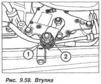
The replacement of the hydraulic control unit of the automatic transmission type "A5S 440Z" must be carried out in the following order. Remove the oil pan of the automatic transmission. Holding the clamping sleeve (1, Fig. 9.59), loosen the nut (2).
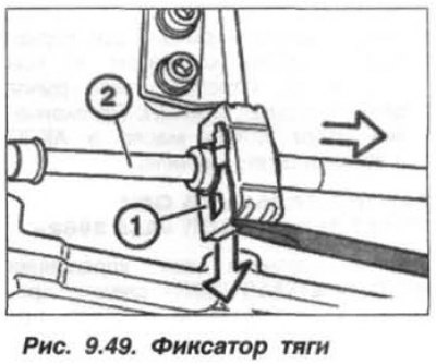
Using a screwdriver, remove the locking plate (1, see Fig. 9.49) and remove the cable (2) from the bracket. Unlock the automatic transmission control shaft and disconnect (undock) his.
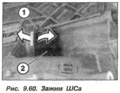
Press the clamp to the right (1, Fig. 9.60) and remove it from the ShSa housing. Press the ShSa housing into the automatic transmission housing.
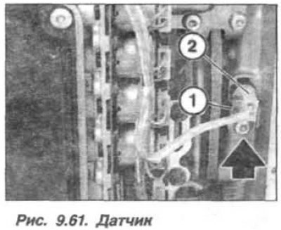
Unscrew the screw, remove the bracket (1, Fig. 9.61) and remove the speed sensor (2) from the automatic transmission housing. Loosen the bolts and remove the oil filter from the automatic transmission hydraulic control unit.
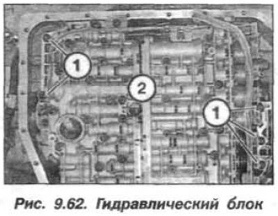
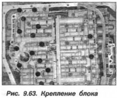
Remove the screws (1, M6x30, 5 pcs.) hydraulic block mounts (2, Fig. 9.62). Remove all large head bolts (16 pcs., black dots, Fig. 9.63), except for the bolt in the middle of the block (1). Holding the hydraulic block, unscrew the last bolts (1) and remove the block from the automatic transmission housing.
 |
 |
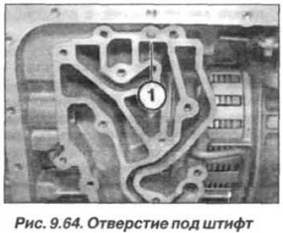
The installation of the hydraulic unit should be carried out in the reverse order, while it is necessary to ensure the presence of the centering pin, which should go into the hole (1, Fig. 9.64) on the automatic transmission housing.
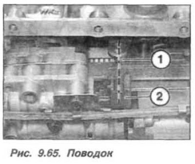
When installing the hydraulic control unit, it is necessary to start the leash (1, Fig. 9.65) selector disc into the groove of the spool rod (2).
Hexagon socket head center bolts (M6x60, 17 pcs.) tighten the hydraulic control unit fasteners to a torque of 8.0 N·m (0.8 kgf·m). Peripheral hexagon socket head bolts (M6x30, 5 pcs.) tighten the hydraulic control unit mountings to a torque of 8.0 N·m (0.8 kgf·m).
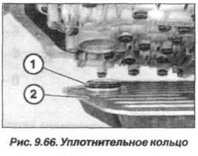
Replace O-ring seals (1, Fig. 9.66) oil filter (2) and lubricate the new ring with petroleum jelly. Tighten the oil filter mounting bolts and the speed sensor bracket mounting bolt to a torque of 5.0 N·m (0.5 kgf·m).
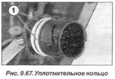
Replace the sealing ring round section (1, Fig. 9.67). To facilitate installation, lubricate the sealing ring (1) with Vaseline. When installing, the locking pin of the SG housing must enter the groove on the automatic transmission housing.
Adjust the control unit lever. After completing the work, check the oil level in the automatic transmission.
Automatic transmission type "A5S 390R"
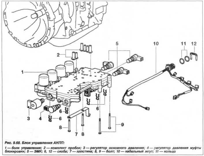
The hydraulic unit (1) for controlling the automatic transmission type "A5S 390R" is shown in Figure 9.68.
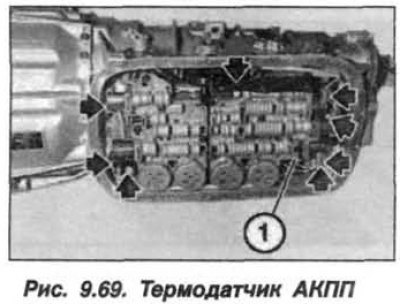
The replacement of the hydraulic control unit of the automatic transmission type "A5S 390R" must be carried out in the following order. Remove the oil pan of the automatic transmission and disconnect all the shock absorbers from the hydraulic control unit. Remove the temperature sensor from the holder (1, Fig. 9.69) Automatic transmission. Since April 2000, the temperature sensor has been built into the wiring harness.
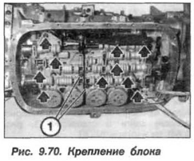
Mark the location of the bolts as they are different lengths. Bolts (1, 2 pcs., Fig. 9.70) do not unscrew. Unscrew all other bolts (arrows) for fastening the hydraulic control unit with the external dimension "Torx E8" and remove the hydraulic unit. The installation of the hydraulic unit should be carried out in the reverse order, while it is necessary.
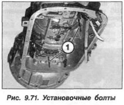
Blow out all threaded connections with compressed air. Screw in the mounting bolts (1, Fig. 9.71) from the sealing kit, into the threaded holes.
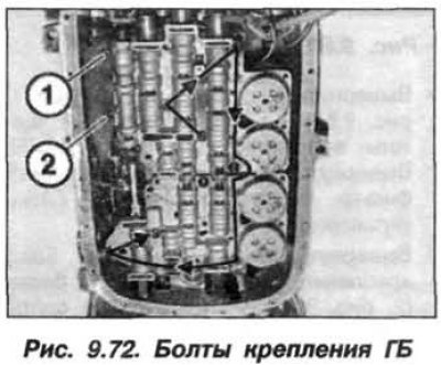
Length of bolts (1 and 2, Fig. 9.72) is 68 mm, the remaining bolts are 58 mm. Install the hydraulic control unit on the two mounting bolts and secure it with the remaining bolts, screwing them in by hand. Remove the two mounting bolts and install the mounting bolts in their place, tightening them by hand. Tighten all the bolts (M6) for fastening the hydraulic unit in the order shown in Figure 9.72 to a torque of 11.0 N·m (1.1 kgf·m). Do not tighten the screws (1 and 2) yet.
Install the guide (1, Fig. 9.73) automatic transmission switch into the retaining spring (2).
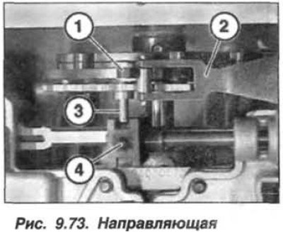
Attention! The disc selector leash (3) must be in the groove (4) of the spool rod.
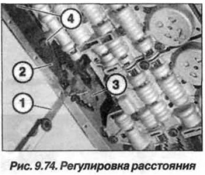
Insert the dipstick (1, Fig. 9.74) between the locking spring (2) and the selector disk (3) and adjust the distance to 0.80 mm by moving the locking spring (2).
Tighten the screws (4, M6) to a torque of 11 N·m (1.1 kgf·m). Upon completion of the work, check the oil level in the automatic transmission and top it up if necessary.
This article is available at russian, bulgarian, belarusian, ukrainian, serbian, croatian, romanian, polish, slovak, hungarian
Article verified: Zhuravleva Isolda
Share information:
Previous articles
БМВ E53: Automatic gearbox
Next articles
Similar articles on other types of BMW cars:
Removal and installation the control unit BMW 3 Series E30 (1982-1994)
Removal and installation the DME control unit BMW 3 Series E36 (1990-2000)
Checking and replacing the pulse sensor and ignition control unit… BMW 5 Series E28 (1981-1988)
On-Board Control System (OBCS) Unit BMW 5 Series E12 (1972-1981)
Replacing the EDC control unit BMW 7 Series E38 (1994-2001)
DME control unit — removal and installation BMW 7 Series E32 (1986-1994)
Replacing the left xenon headlight control unit (up to 09/2006) BMW X3 E83 (2003-2010)
Link in different formats to this page
Visitor comments
No comments yet
- General information
- Manual
- Maintenance
- M54 petrol engine
- Engine repair
- Lubrication system
- Cooling system
- Supply system
- Injection system
- Exhaust system
- Engine electrics
- M62 petrol engine
- Engine repair
- Lubrication system
- Cooling system
- Supply system
- Exhaust system
- Engine electrics
- N62 petrol engine
- Engine repair
- Cooling and lubrication system
- Power and exhaust system
- Engine electrics
- Diesel engine M57
- Engine repair
- Lubrication system
- Cooling system
- Power and exhaust system
- Engine electrics
- Turbocharging system
- Transmission
- Clutch
- Mechanical gearbox
- Automatic gearbox
- Transfer case and cardan
- Chassis
- Brake system
- Steering
- Front suspension
- Rear suspension
- Wheels and tires
- Body
- Exterior
- Interior
- Doors and windows
- Repair and maintenance
- Heater and air conditioner
- Electrical equipment
- Equipment and devices
- Levers and switches
- Electrical circuits