
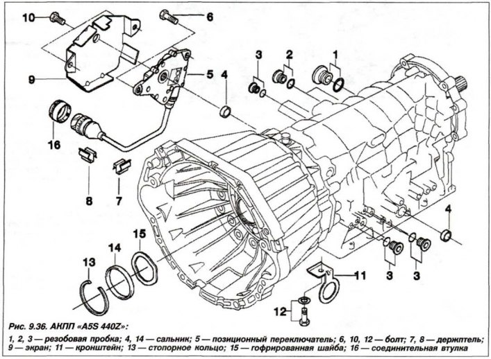
Automatic transmission type «A5S 440Z»
Replacing the position switch automatic transmission type «A5S 440Z» must be done in the following order.
All work on replacing the position switch should be carried out on a cold engine due to the possibility of burns on the elements of the exhaust system. Remove bolts (10, fig. 9.36) and remove the protective cover (9) position switch (5). Remove bolts (6) and remove the position switch (5) from the axis of the lever of the control unit.
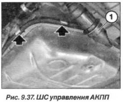
Unlock loop (1, fig. 9.37) automatic transmission control. Remove the loop from the holder and release the cable harness from the brackets on the automatic transmission oil sump.
Installation of the position switch must be carried out in the reverse order, with the screws (M6) tighten its fasteners with a torque of 10 Nm (1.0 kgf·m).
Automatic transmission type «A5S 390R»
All work on replacing the position switch should be carried out on a cold engine due to the possibility of burns on the elements of the exhaust system.
Attention! Do not remove the transmission lock bar in the parking lot, mode «R».
Do not move the transmission lock bar on the riser by more than 10 mm; if necessary, fix the bar with tongs.
Replacing the position switch automatic transmission type «A5S 390R» must be done in the following order. Remove the automatic transmission oil sump and set the automatic transmission control selector to position «D». Remove the automatic transmission hydraulic control unit.
Holding the clamping sleeve (1, see fig. 9.4) from turning and loosen the nut (2).
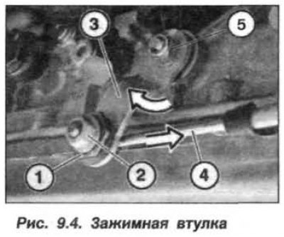
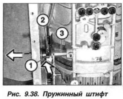
Loosen the nut (5) and remove the lever (3) control unit. Press out spring pin (1, fig. 9.38) switch (2) automatic transmission. Disconnect the selector dial from the parking lock bar. Remove switch (2) Automatic transmission with selector dial.
Remove switch (1, fig. 9.39) Automatic transmission from the selector disk.
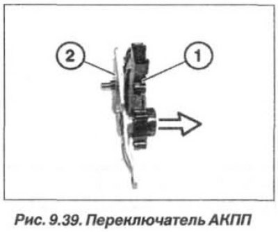
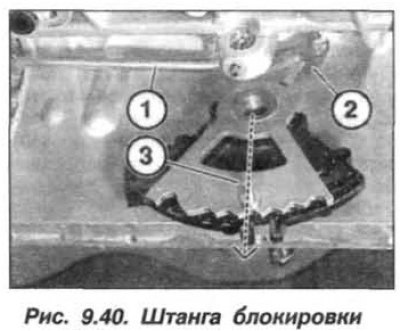
The installation of the position switch should be carried out in the reverse order, while it is necessary to start the rod (1, fig. 9.40) transmission lock in the parking lot from the rear to the selector dial (2). Insert the axis of the lever of the control unit.
Holes for spring pins in switch (1, see fig. 9.39) automatic transmission, in selector disk (2) and in the axis of the lever of the control unit must overlap. Press in the spring pin.
Attention! During the entire installation operation, the leash (3) must be located strictly perpendicular to the axis of the lever of the control unit.
After installing the detent spring, check that the parking lock system is working. Why wring out the leash (3) forward into position «R», turn the cardan shaft and check the fixation of the pawl.
Tighten the control unit lever mounting nut to 15 Nm (1.5 kgf·m). Adjust control box lever. Tighten the clamping sleeve nut to a torque of 10 Nm (1.0 kgf·m).
Upon completion of work, check the oil level in the automatic transmission and, if necessary, restore it.