
Attention! The automatic transmission should be removed only after the cause of the malfunction on the car has been precisely determined.
Mark the position of the bolts, as they have different diameters and lengths. When installing the automatic transmission, replace all seals, self-locking nuts, bolts and washers with new ones.
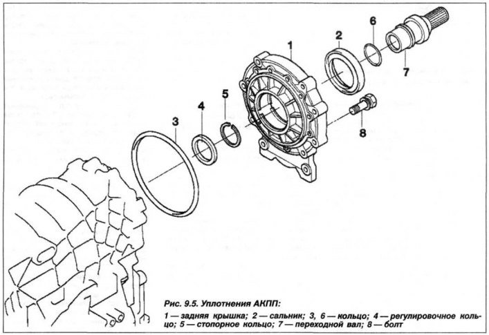
Replacement of automatic transmission "A5S 440Z"
The sealing elements of the rear cover of the automatic transmission are shown in Figure 9.5. The automatic transmission must be removed in the following order. Prepare the tools "00.2.030", "24.0.250", "24.1.110", "24.4.131", "24.2.300", "24.4.132", "24.5.301" and "24.5.307". Disconnect the power supply and remove the ignition key. Disconnect the wire from the "–" terminal of the battery, which is located behind the right side trim of the trunk.
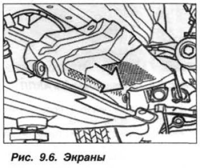
Remove the front engine sump guard panel, the stiffening plate and the left and right heat-insulating shields (Fig. 9.6). Disconnect the oxygen sensor circuits in the exhaust gas and remove the exhaust system.
Release the wires of the oxygen content sensors in the exhaust gas from the clamps, disconnect the nuts on both sides of the rod from the anti-roll bar. Hold the rod of the ball head with an open-end wrench by the "flats". Move the stabilizer forward and remove the rear heat-insulating screen.
Mark the relative positions of the engine/automatic transmission and the automatic transmission mounting bolts with paint or a marker to facilitate subsequent assembly.
Loosen the mounting bolts and disconnect the cardan joint disk from the automatic transmission. Rotate only the nuts, holding the bolt heads. Move the cardan shaft to the side and secure it to the body with a wire clamp, preventing it from breaking at the joint.
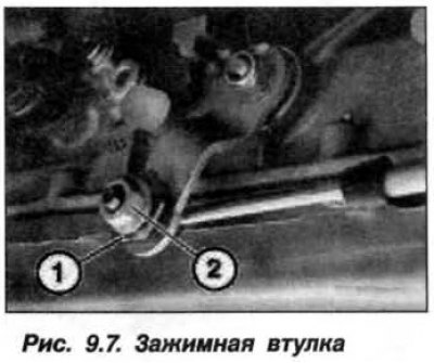
Release from the bracket (on the engine) automatic transmission ventilation pipe. Holding the clamping sleeve (1, Fig. 9.7), loosen the clamping nut (2).
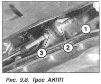
Holding the rope (1, Fig. 9.8) from turning by the hex head (2), unscrew the nut (3) and remove the cable from the mounting bracket.
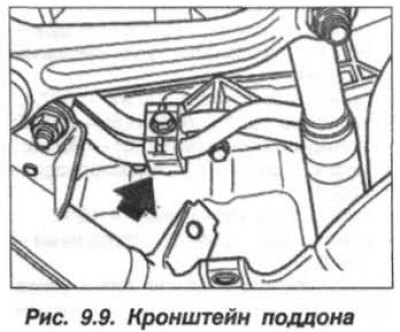
Disconnect the oil line mounting bracket (arrow, Fig. 9.9) from the oil pan. Disconnect the oil line mounting bracket from the power steering pump.
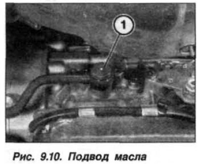
Install the oil collection pan. Remove the hollow bolt (1, Fig. 9.10) oil supply and disconnect the oil line.
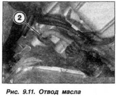
Unscrew the coupling (2, Fig. 9.11) oil drain and disconnect the oil line. Move both oil lines to the left.
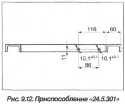
Attention! The "24.5.301" device must have two holes with a diameter of 10.1–10.2 mm (Fig. 9.12). Only such a device ensures a stable position of the automatic transmission and transfer case (TC) unit on the "24.0.250" device.
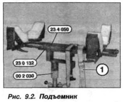
Put the devices together "24.5.301", "00.2.030" and "24.0.250", for which insert the hinge pin into the rear hole of the "24.5.301" device. Support the automatic transmission and transfer case with the assembly of devices (see fig. 9.2).
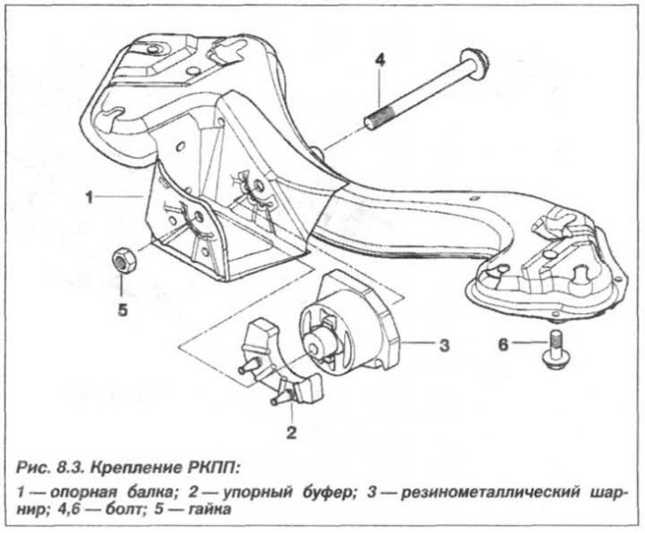
Release the harness of the oxygen concentration sensors in the exhaust gas from the holders on the crossbar of the automatic transmission mount and remove it from the holders on the automatic transmission housing. Unscrew the bolts (6, see Fig. 8.3) and disconnect the automatic transmission mounting cross beam from the body.
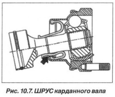
Attention! Avoid dropping the cardan shaft, otherwise the CV joint and rubber seal may be damaged (arrow, see Fig. 10.7).
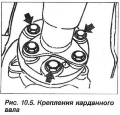
Loosen the elastic coupling fastening nuts (arrows, see Fig. 10.5) and remove the bolts.
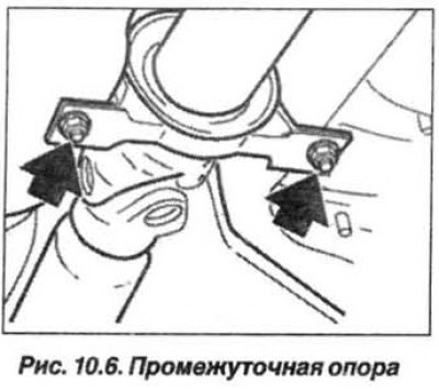
Holding the cardan shaft by the intermediate support, unscrew the nuts (arrows, see Fig. 10.6) its fastening. Press the intermediate support of the cardan shaft downwards and disconnect the cardan shaft from the flange of the secondary shaft of the automatic transmission. Move the cardan shaft to the side and secure it to the body with a wire clamp.
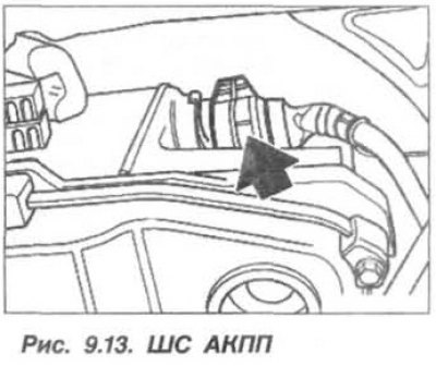
Disconnect the automatic transmission control system (Fig. 9.13), install a polyethylene cover on the control system, remove the cable from the holders on the automatic transmission housing and secure it to the body with tape or a wire clip.
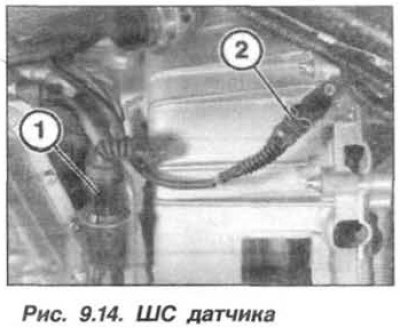
Undock the SS (1, Fig. 9.14) and disconnect it. Cover the SS with a polyethylene cover and secure it to the body with tape or a wire clip. Disconnect the SS (2) of the engine shaft speed sensor, cover the IIIS with a polyethylene cover and secure it to the body with tape or a wire clip.
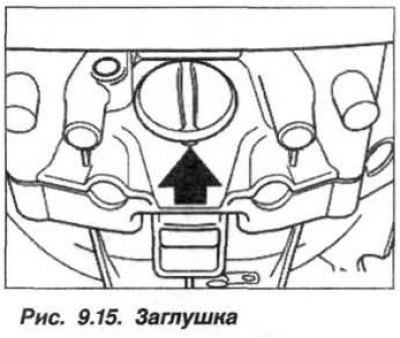
Remove the protective cover (plug) from the hole in the rear lower part of the cylinder block crankcase (arrow, Fig. 9.15) engine.
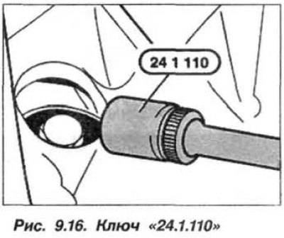
Unscrew the torque converter mounting bolts to the engine drive disk in order using the "24.1.110" key (Fig. 9.16). To bring the bolt to the hole, turn the engine shaft clockwise by the crankshaft pulley bolt. Make sure that the bolts do not fall inside the block.
Unload the automatic transmission by slightly lifting it with a garage jack, through a wooden pad under the crankcase, but not for the automatic transmission oil pan. Install, through a wooden pad, a second garage jack under the engine in the area of the first cylinder or use a lift (see fig. 9.2). This will prevent it from tipping over when the automatic transmission is removed.
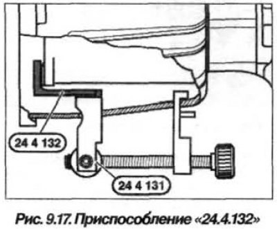
Slightly lower the automatic transmission. Turn the front wheels so that when lowering the automatic transmission, the transverse steering rod is not under load. Take measures to prevent the torque converter from slipping. To do this, install the devices "24.4.131" and "24.4.132" (Fig. 9.17) in the automatic transmission housing window and tighten it.
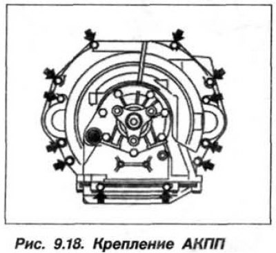
Loosen the bolts crosswise (arrows, Fig. 9.18) attach the automatic transmission to the engine and remove them completely. In this case, the automatic transmission relies on a jack or device. Together, with an assistant, disconnect the engine and automatic transmission together RC, moving them on themselves. Remove the automatic transmission and RC from under the vehicle. Disconnect the RC from the automatic transmission.
Attention! Install only standard engine, automatic transmission and torque converter mounting bolts.
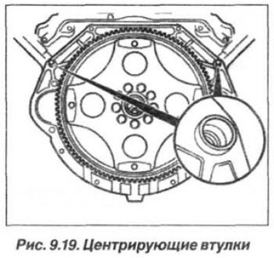
The automatic transmission should be installed in the reverse order, while checking the installation of the centering bushings (arrows, Fig. 9.19). Replace damaged bushings.
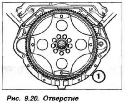
Check the condition of the hole (1, Fig. 9.20) access to the compensating coupling.
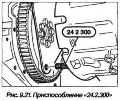
Screw the "24.2.300" tool into the threaded hole (1, Fig. 9.21) on the torque converter. Turn the torque converter until the "24.2.300" device is aligned with the hole in the compensating coupling.
Fasten the automatic transmission and engine flanges by screwing in the mounting bolts and tightening them tightly by hand.
Tighten three torque converter mounting bolts to the engine drive plate to a torque of 10–15 N·m (1.0–1.5 kgf·m). Unscrew the "24.2.300" tool and install the fourth torque converter mounting bolt to the engine flywheel plate. Tighten all torque converter mounting bolts to a torque of 45 N·m (4.5 kgf·m).
Check the mating of the automatic transmission and the engine. Return the mounting bolts, together with the washers (according to marking), and first, on the principle of every other one, tighten all the bolts to a torque of 20 N·m (2.0 kgf·m) and remove the devices "24.4.131" and "24.4.132".
Further tightening of the bolts securing the automatic transmission to the engine should be carried out in several steps crosswise, with the final torque specified below, N·m/kgf·m:
- torx type bolts:
- m8 21/2.1;
- m10 42/4.2;
- hex head bolts:
- m8 24/2.4;
- m10 45/4.5;
- cross beam bolts – 41/4.1;
- oil line mounting bolts – 28/2.8 (replace o-rings);
- automatic transmission shock absorber nut – 74/7.4;
- filler plug (M18x1.5) – 35/3.5;
- drain plug (M16x1.5) – 30/3.0;
- drain pipe coupling – 28/2.8;
- control cable nut – 15/1.5;
- nut (M8) of the control lever – 10/1.0.
Adjust the control unit balancer. When installing the removed elements, it is prohibited to apply significant force so that the parts are not subjected to excessive mechanical loads. Replace the automatic transmission sealing elements. Add oil to the automatic transmission and install the cardan shaft.
Attention! When tightening the bolts securing the elastic coupling and the rubber-metal shock absorber, only turn the nuts and hold the bolts with a wrench to avoid creating stress in the coupling body.
Install the crossmember on the automatic transmission and the body bottom. Tighten the bolts to a torque of 41 N·m (4.1 kgf·m). Tighten the new nut of the rubber-metal shock absorber mounting bolt to a torque of 74 N·m (7.4 kgf·m).
Tighten the new nuts of the elastic coupling mounting bolts to a torque of 100.0 N·m (10.0 kgf·m).
Tighten the intermediate support mounting nuts to a torque of 21.0 N·m (2.1 kgf·m).
Install the anti-roll bar onto the push rods and secure it with new self-locking nuts, with a tightening torque of 6.0 kgf·m (60 N·m).
Install all removed components in place. When replacing the speed sensor on a new automatic transmission, it must be reconfigured.
Check the oil level in the automatic transmission. Fasten the stiffening plate in two successive steps - with a torque of 56 N·m (5.6 kgf·m) and turn it by an angle of 90°.
If necessary, adjust the gearshift drive and test drive the vehicle with all possible gearshift options.