
Table of contents: Removal ↓ Installation ↓
- Home
- BMW 3 Series
- E46
- Transmission
- Car gearbox
- Removal and installation of automatic transmission
Removal and installation of automatic transmission (BMW 3 Series E46)
To remove the car, it must be raised to the required height. In addition, to lower the box, a suitable garage lift is required. The instructions below apply to removing the manual transmission. The differences when removing the automatic transmission will be discussed additionally.
1. Disconnect the negative (-) battery cable with the ignition off. The battery is located in the luggage compartment behind the cover on the right side. In BMW 316i, 318i cars, the battery is located in the engine compartment.
2. Models 316i, 318i: Loosen the mounting bolts and remove the ignition coils from the holders, moving them to the side so as not to damage the ignition cables when removing the manual transmission.
3. Models 320i, 323i, 328i: Remove the fan with the holder from the radiator and move it slightly upwards, refer to Section Removal and installation the fan/fan shroud.
4. Models 320d, 320i, 323i, 328i: Remove the air box, refer to Section Removal and installation the air intake box.
5. Remove the lower engine compartment cover, refer to Section Removal and installation the lower engine compartment cover.
6. Remove the front part of the vehicle amplifier, refer to Section Removal and installation the front suspension beam.
7. Loosen the mounting bolts and remove the intake pipe from the exhaust manifold, refer to Section Removal and installation of the exhaust system.
8. Disconnect the heat shield of the exhaust system in the area of the manual transmission from the bottom of the car.
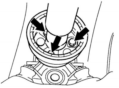
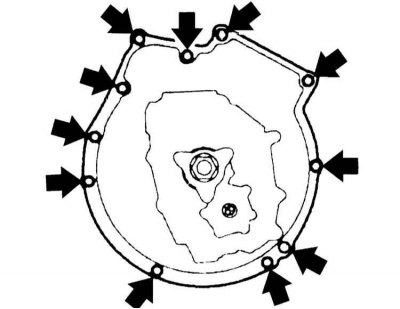
9. Disconnect the universal joint flange from the manual transmission (arrows in the illustration). To avoid overtightening the flange, when loosening, turn only the nuts, not the bolts.
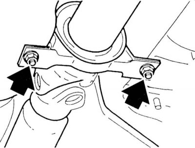
10. Loosen the mounting bolts and remove the central bearing of the propeller shaft (arrows in the illustration). While doing this, hold the shaft so that it does not fall.
11. Remove the propeller shaft from the manual transmission flange.
When removing the clutch slave cylinder, slowly unload the rod, otherwise air will enter through the seal. Hang the cylinder with the hose attached on a wire to the body. If air enters the hydraulic system, air must be removed from the system after installation.
12. Remove the slave cylinder, refer to Section Removal and installation the clutch slave cylinder.
13. Raise the manual transmission a little with a garage lift and support it.
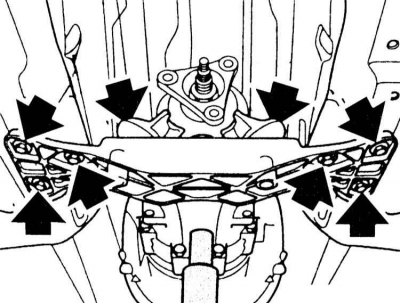
14. Unscrew the mounting bolts and disconnect the crossmember at the bottom and the manual transmission.
15. Slowly lower the manual transmission using a garage lift until the engine almost touches the wall of the engine compartment.
16. Support the engine from the front with a second lift so that it cannot tip over after the manual transmission is removed.
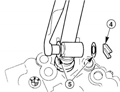
17. Remove the locking brackets "4" on the shift rod from the manual transmission side and the shift lever. Remove the washers "5" of the shift rod, remove the rod.
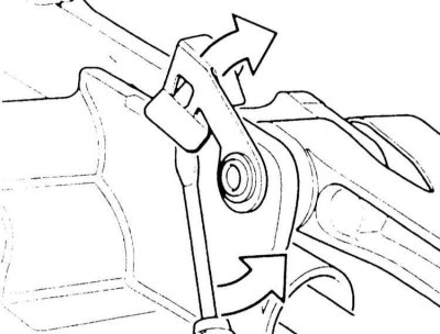
18. Use a screwdriver to push the retainer of the support pin of the shift rod on the box upwards. Remove the pin from the side.
19. Disconnect the reverse switch connector on the transmission. Release the reverse light and oxygen sensor cables from the holders on the transmission.
20. Remove the fan with the holder from the radiator and pull it up a little. Remove the air box, refer to Section Removal and installation the air intake box.
21. Remove the gear selector cable on the transmission, refer to Section Adjusting the selector rod.
22. Disconnect the connector on the box by turning the nut on the plug to the left.
23. Disconnect the holder at the oil pan for the AT radiator oil lines.
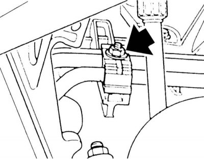
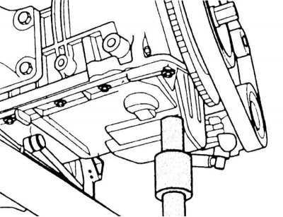
24. Disconnect the radiator oil line holder from the box (arrow on the illustration), remove the oil lines.

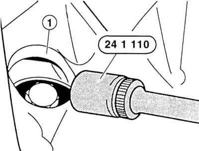
25. Remove the cover of the hole "1" at the crankcase of the cylinder block. Unscrew the 3 torque converter mounting bolts one after the other using a narrow head, for example, BMW 24 1 110 or some similar tool. Make sure that the bolts do not fall into the crankcase. To ensure that the bolts are in the groove, turn the engine by the hexagon of the crankshaft pulley.
26. Support the box with a lift from underneath the car. You can only support it in the area of the box housing, not the oil pan.
27. Unscrew the bolts securing the gearbox to the engine. The location of the flange bolts corresponds to the location of the gearbox mounting bolts.
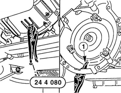
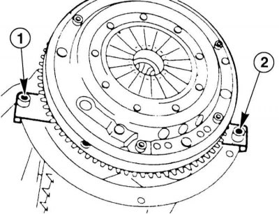
28. Make sure that the converter does not slip out. To do this, place clamp "1" at the box housing with the flat side facing the converter and clamp it. If it is impossible to install the specified clamp, make sure that the converter does not slip out of the box when removing the box. Disconnect the box from the engine.
29. Remove the Torx screws securing the gearbox flange (arrows in the illustration).
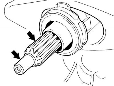
30. Remove the gearbox from the guide bushings and input shaft and remove it with the help of an assistant.
31. Before installation, check the clutch, refer to Section Removal and installation the clutch.
32. Check the ease of movement of the clutch release bearing. Lubricate the mating surfaces of the release lever with grease "ESSO UNIREX S2".
33. Wipe the grease off the splines of the input shaft with a rag. Then apply a thin layer of grease "ESSO UNIREX S2". Do not apply too much grease, as it may get on the friction surfaces and cause the clutch to fail to engage. The required amount of grease corresponds to the size of a grain of rice.
34. Engage the gear lever.
35. Make sure that both guide bushings "1" and "2" between the engine and the gearbox are in place. Lift the gearbox and insert it horizontally into the clutch. If the gearbox shaft does not enter the clutch driven disc during installation, turn the shaft by hand from behind the flange of the cardan shaft.
36. Screw in the flange mounting bolts with washers. Tightening torques are given in Specifications.
37. Lubricate the shift rod support pin with grease "KLUBER POLYLUB GLY 801" and insert. Push the finger retainer down.

38. Place the washers on the pin, observing the correct position. The large surface of the washers "5" is adjacent to the shift rod. Install the rod on the gearshift lever and gearbox lever and secure with locking brackets.
39. Connect the reverse switch connector and secure it. Route the reverse light and oxygen sensor cables in the holders on the box.
40. Install the clutch slave cylinder, refer to Section Removal and installation the clutch slave cylinder.
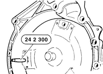
41. Turn the torque converter on the box so that the holes on the bars point towards the center of the holes on the flywheel. Screw the BMW 24 2 300 tool into the bar.
42. When connecting the engine and gearbox, the three mounting strips on the converter must match the three protrusions on the engine flywheel. Subsequent changes in position are impossible and may cause damage.
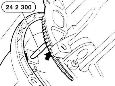
43. Install the automatic transmission and carefully insert the 24 2 300 tool into the hole on the driven disk. After securing the transmission, pull the tool forward from the bar (arrow on the illustration).
44. Remove the clamp from the gearbox housing and screw the three torque converter mounting bolts into the gearbox holes. Tighten the bolts to 45 N·m. Use only original bolts.
45. Remove the protective film and connect the oil lines to the box, securing them in the holder. Replace the sealing gaskets.
46. Secure the oil line holders to the oil pan.
47. Connect the connector to the box, it should lock into place.
48. Install the selector and adjust it, refer to Section Adjusting the selector rod.
49. Raise the box with a jack and secure the beam to the bottom and box with the forces specified in the Specifications.
50. Remove the jack.
51. Secure the cardan shaft to the gearbox flange with new self-locking nuts. The tightening torque of the threaded connections depends on the strength class of the bolts, which is stamped on the bolt head (refer to Specifications).
52. Tighten the propeller shaft central bearing mounting bolts to a torque of 20 Nm.
53. Lightly tighten the screw ring on the movable element of the propeller shaft to a torque of 10 Nm.
54. Attach the heat shield to the underbody. Install the exhaust system, refer to Section Removal and installation of the exhaust system.
55. Fill the AT with oil, refer to Section Checking the level/changing the oil in the rear axle gearbox.
56. Install the front reinforcement, refer to Section Removal and installation the front suspension beam.
57. Models 320i, 323i, 328i: Attach the fan with the holder to the radiator, refer to Section Removal and installation the fan/fan shroud.
58. Models 320d, 320i, 323i, 328i: Install the air collection box, refer to Section Removal and installation the air intake box.
59. Secure the lower engine compartment cover.
60. Models 316i, 318i: Secure to ignition coil holder.
61. Connect the negative (-) battery cable with the ignition off. Set the clock.
Removal
1. Disconnect the negative (-) battery cable with the ignition off. The battery is located in the luggage compartment behind the cover on the right side. In BMW 316i, 318i cars, the battery is located in the engine compartment.
Disconnecting the battery will erase the fault memory of some control units. If necessary, read the fault memory before disconnecting the battery. Refer to Section Troubleshooting. It is advisable to carry out the work in a service station.
2. Models 316i, 318i: Loosen the mounting bolts and remove the ignition coils from the holders, moving them to the side so as not to damage the ignition cables when removing the manual transmission.
3. Models 320i, 323i, 328i: Remove the fan with the holder from the radiator and move it slightly upwards, refer to Section Removal and installation the fan/fan shroud.
4. Models 320d, 320i, 323i, 328i: Remove the air box, refer to Section Removal and installation the air intake box.
Lifting and placing the vehicle on stands is dangerous! Therefore, please read Section Jacking and towing
5. Remove the lower engine compartment cover, refer to Section Removal and installation the lower engine compartment cover.
6. Remove the front part of the vehicle amplifier, refer to Section Removal and installation the front suspension beam.
7. Loosen the mounting bolts and remove the intake pipe from the exhaust manifold, refer to Section Removal and installation of the exhaust system.
8. Disconnect the heat shield of the exhaust system in the area of the manual transmission from the bottom of the car.
9. Disconnect the universal joint flange from the manual transmission (arrows in the illustration). To avoid overtightening the flange, when loosening, turn only the nuts, not the bolts.
10. Loosen the mounting bolts and remove the central bearing of the propeller shaft (arrows in the illustration). While doing this, hold the shaft so that it does not fall.
11. Remove the propeller shaft from the manual transmission flange.
When removing the clutch slave cylinder, slowly unload the rod, otherwise air will enter through the seal. Hang the cylinder with the hose attached on a wire to the body. If air enters the hydraulic system, air must be removed from the system after installation.
12. Remove the slave cylinder, refer to Section Removal and installation the clutch slave cylinder.
13. Raise the manual transmission a little with a garage lift and support it.
14. Unscrew the mounting bolts and disconnect the crossmember at the bottom and the manual transmission.
15. Slowly lower the manual transmission using a garage lift until the engine almost touches the wall of the engine compartment.
16. Support the engine from the front with a second lift so that it cannot tip over after the manual transmission is removed.
17. Remove the locking brackets "4" on the shift rod from the manual transmission side and the shift lever. Remove the washers "5" of the shift rod, remove the rod.
18. Use a screwdriver to push the retainer of the support pin of the shift rod on the box upwards. Remove the pin from the side.
19. Disconnect the reverse switch connector on the transmission. Release the reverse light and oxygen sensor cables from the holders on the transmission.
20. Remove the fan with the holder from the radiator and pull it up a little. Remove the air box, refer to Section Removal and installation the air intake box.
21. Remove the gear selector cable on the transmission, refer to Section Adjusting the selector rod.
22. Disconnect the connector on the box by turning the nut on the plug to the left.
23. Disconnect the holder at the oil pan for the AT radiator oil lines.
24. Disconnect the radiator oil line holder from the box (arrow on the illustration), remove the oil lines.
Place a container underneath to collect the leaking oil. Do not allow dirt to get into the pipes, so cover them with plastic bags with rubber bands.
25. Remove the cover of the hole "1" at the crankcase of the cylinder block. Unscrew the 3 torque converter mounting bolts one after the other using a narrow head, for example, BMW 24 1 110 or some similar tool. Make sure that the bolts do not fall into the crankcase. To ensure that the bolts are in the groove, turn the engine by the hexagon of the crankshaft pulley.
26. Support the box with a lift from underneath the car. You can only support it in the area of the box housing, not the oil pan.
27. Unscrew the bolts securing the gearbox to the engine. The location of the flange bolts corresponds to the location of the gearbox mounting bolts.
28. Make sure that the converter does not slip out. To do this, place clamp "1" at the box housing with the flat side facing the converter and clamp it. If it is impossible to install the specified clamp, make sure that the converter does not slip out of the box when removing the box. Disconnect the box from the engine.
29. Remove the Torx screws securing the gearbox flange (arrows in the illustration).
30. Remove the gearbox from the guide bushings and input shaft and remove it with the help of an assistant.
When removing and installing the gearbox, do not allow it to hang on the input shaft, as this may damage the clutch driven disc. Pull the gearbox back as far as possible, turn it approximately 10° counterclockwise and remove.
Installation
31. Before installation, check the clutch, refer to Section Removal and installation the clutch.
32. Check the ease of movement of the clutch release bearing. Lubricate the mating surfaces of the release lever with grease "ESSO UNIREX S2".
check the grease in the spline grooves of the input shaft. If the grease is sticky, the clutch driven disc must be replaced, refer to Section Removal and installation the clutch.
33. Wipe the grease off the splines of the input shaft with a rag. Then apply a thin layer of grease "ESSO UNIREX S2". Do not apply too much grease, as it may get on the friction surfaces and cause the clutch to fail to engage. The required amount of grease corresponds to the size of a grain of rice.
34. Engage the gear lever.
35. Make sure that both guide bushings "1" and "2" between the engine and the gearbox are in place. Lift the gearbox and insert it horizontally into the clutch. If the gearbox shaft does not enter the clutch driven disc during installation, turn the shaft by hand from behind the flange of the cardan shaft.
36. Screw in the flange mounting bolts with washers. Tightening torques are given in Specifications.
37. Lubricate the shift rod support pin with grease "KLUBER POLYLUB GLY 801" and insert. Push the finger retainer down.
38. Place the washers on the pin, observing the correct position. The large surface of the washers "5" is adjacent to the shift rod. Install the rod on the gearshift lever and gearbox lever and secure with locking brackets.
39. Connect the reverse switch connector and secure it. Route the reverse light and oxygen sensor cables in the holders on the box.
40. Install the clutch slave cylinder, refer to Section Removal and installation the clutch slave cylinder.
41. Turn the torque converter on the box so that the holes on the bars point towards the center of the holes on the flywheel. Screw the BMW 24 2 300 tool into the bar.
42. When connecting the engine and gearbox, the three mounting strips on the converter must match the three protrusions on the engine flywheel. Subsequent changes in position are impossible and may cause damage.
43. Install the automatic transmission and carefully insert the 24 2 300 tool into the hole on the driven disk. After securing the transmission, pull the tool forward from the bar (arrow on the illustration).
44. Remove the clamp from the gearbox housing and screw the three torque converter mounting bolts into the gearbox holes. Tighten the bolts to 45 N·m. Use only original bolts.
45. Remove the protective film and connect the oil lines to the box, securing them in the holder. Replace the sealing gaskets.
46. Secure the oil line holders to the oil pan.
47. Connect the connector to the box, it should lock into place.
48. Install the selector and adjust it, refer to Section Adjusting the selector rod.
49. Raise the box with a jack and secure the beam to the bottom and box with the forces specified in the Specifications.
50. Remove the jack.
51. Secure the cardan shaft to the gearbox flange with new self-locking nuts. The tightening torque of the threaded connections depends on the strength class of the bolts, which is stamped on the bolt head (refer to Specifications).
52. Tighten the propeller shaft central bearing mounting bolts to a torque of 20 Nm.
53. Lightly tighten the screw ring on the movable element of the propeller shaft to a torque of 10 Nm.
54. Attach the heat shield to the underbody. Install the exhaust system, refer to Section Removal and installation of the exhaust system.
55. Fill the AT with oil, refer to Section Checking the level/changing the oil in the rear axle gearbox.
56. Install the front reinforcement, refer to Section Removal and installation the front suspension beam.
57. Models 320i, 323i, 328i: Attach the fan with the holder to the radiator, refer to Section Removal and installation the fan/fan shroud.
58. Models 320d, 320i, 323i, 328i: Install the air collection box, refer to Section Removal and installation the air intake box.
59. Secure the lower engine compartment cover.
60. Models 316i, 318i: Secure to ignition coil holder.
61. Connect the negative (-) battery cable with the ignition off. Set the clock.
This article is available at russian, bulgarian, belarusian, ukrainian, serbian, croatian, romanian, polish, slovak, hungarian
Article verified: Sevastyanov Nikolay
Share information:
Previous articles
БМВ E46: Car gearbox
Next articles
Similar articles on other types of BMW cars:
Removal and installation of automatic transmission BMW 5 Series E28 (1981-1988)
Removal and installation the cardan transmission BMW 5 Series E12 (1972-1981)
Automatic transmission — removal and installation BMW 7 Series E32 (1986-1994)
Removal and installation of manual transmission BMW 7 Series E38 (1994-2001)
Pistons — removal and installation BMW X3 E83 (2003-2010)
Removal and installation of automatic transmission type A5S 440Z BMW X5 E53 (1999-2006)
Link in different formats to this page
Visitor comments
No comments yet
- General information
- Manual
- Maintenance
- Power unit
- Engine repair
- Cooling system
- Power system (gasoline)
- Injection system (gasoline)
- Fuel system (diesel)
- Exhaust system
- Ignition system
- Charge and launch systems
- Transmission
- Car gearbox
- Clutch and drive shafts
- Chassis
- Brake system
- Suspension front and rear
- Steering
- Body
- Body care and repair
- Exterior
- Interior
- Electrical equipment
- Troubleshooting
- Lighting and signaling
- Equipment and devices
- Heater and air conditioner
- Electrical circuits
- General information
- Manual
- Repair on the road
- Weekly checks
- Maintenance
- Troubleshooting
- Power unit
- 4 cylinder engines
- 6 cylinder engines
- Engine overhaul
- Cooling and heating
- Fuel and exhaust system
- Starting and charging system
- Ignition system
- Transmission
- Clutch
- Mechanical gearbox
- Automatic gearbox
- Cardan and drive shafts
- Chassis
- Brake system
- Wheel suspension
- Steering
- Body
- Exterior
- Interior
- Electrical equipment
- Equipment and devices
- Electrical circuits
- General information
- Maintenance
- Power unit
- Engine repair
- Cooling system
- Ignition system
- Supply system
- Fuel injection system
- Exhaust system
- Transmission
- Clutch
- Car gearbox
- Front and rear axle
- Chassis
- Steering
- Brake system
- Body
- Exterior
- Interior
- Electrical equipment
- Heating system
- Equipment and devices
- Power devices
- Electrical circuits
- Power unit
- M10/M20 engine
- M40 engine
- Ignition system
- Lubrication system
- Cooling system
- Supply system
- Fuel injection
- Exhaust system
- Transmission
- Clutch
- Manual gearbox
- Front axle
- Rear axle
- Chassis
- Steering
- Brake system
- Body
- Exterior
- Interior
- Electrical equipment
- Heating system
- Equipment and devices
- Electrical circuits
- General information
- Specifications
- Operation and maintenance
- 4-cylinder engine
- Engine repair
- Cooling and lubrication system
- Supply system
- Ignition system
- 6-cylinder engine
- Engine repair
- Cooling and lubrication system
- Supply system
- Fuel injection system
- Ignition system
- Transmission
- Clutch
- 4-speed manual gearbox
- 5-speed manual gearbox
- Automatic gearbox
- Cardan and rear axle
- Chassis
- Steering
- Front suspension
- Rear suspension
- Brake system
- Electrical equipment
- Equipment and devices
- Electrical circuits