
Table of contents: Removal ↓ Installation ↓
- Home
- BMW 5 Series
- E28
- Transmission
- Transmission line
- Removal and installation the propeller shaft
Removal and installation the propeller shaft (BMW 5 Series E28)
Removal
1. Block the front wheels, then jack up the rear of the vehicle and secure it on axle stands. Remove the exhaust system (see chapter Exhaust system). Remove the exhaust system heat shield.
2. Loosen the clamping sleeve on the sliding sleeve (if provided) a few turns, but do not remove it.
3. The latest models are not equipped with a clamping sleeve. Use paint, a center punch or a scriber to make alignment marks on the transmission flange and the flexible coupling (or front universal joint on some models), and also on the rear universal joint and differential input flange, so that during assembly it is possible to install the transmission in its previous position...
...as well as the rear universal joint and differential input flange
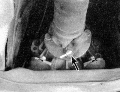
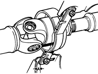
4. Loosen the bolts and nuts securing the elastic coupling (see illustration) or cardan joint (see illustration above) to the transmission output flange. Do not separate the driveshaft from the flange yet.
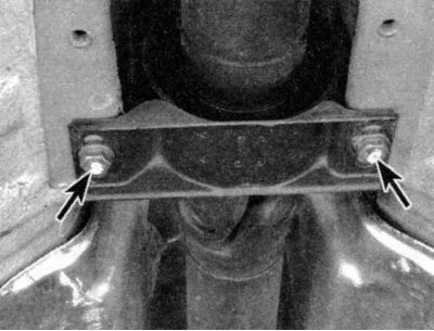
5. On CV joint models, first use a suitable jack to support the transmission. Loosen the rear transmission mount nuts and bolts (see chapter Manual transmission (MT)), then move the support back and loosen the six nuts and bolts securing the CV joint to the transmission support. Loosen the nuts and bolts on the rear flange of the propeller shaft (see illustration above).
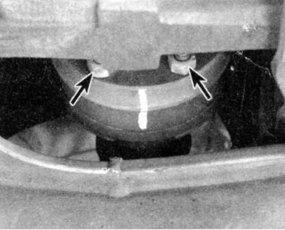
6. Support the cardan shaft at the central bearing and loosen the bolts (indicated by arrows) on bearing assembly
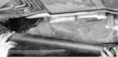
7. Tilt the driveshaft down at the center bearing, then remove it from the center pin on the transmission flange - remove the splined coupling as well if more space is required, but do not separate the driveshaft sections.
On models with a vibration damper, rotate the damper assembly 60° before removing it from the centering pin on the transmission flange.
8. If you are going to clean the spline coupling or replace the rubber bushing, mark both sections of the driveshaft before separating the coupling. After cleaning the splines, lubricate them with molybdenum disulfide grease before reassembling. If you have separated the sections of the driveshaft without marking them, reassemble the spline coupling so that the universal joints are in the same plane. If the driveshaft vibrates after installation, you have installed its sections incorrectly. In this case, you should remove the driveshaft, separate it at the spline coupling, and rotate one section 180° before installing.
Installation
Installation is basically the same as removal in reverse order. However, the following points should be noted.
1. Apply a thin coat of molybdenum disulfide grease to the centering pin on the transmission flange.
2. Place the driveshaft first against the differential input flange, place it on the centering pin on the transmission flange, then place the center bearing against the pin and loosely screw in the mounting bolts. Where the CV joints are installed, make sure the shims are in good condition, otherwise replace them. Align the marks made during disassembly on the rear universal joint flange and the differential input flange. Install the rear section of the driveshaft into the differential input flange using NEW self-locking nuts and tighten these nuts to the specified torque.
Do not reuse self-locking nuts.
3. Align the marks made during disassembly on the front part of the propeller shaft and connect the flexible coupling, universal joint or CV joint to the transmission output shaft using new self-locking nuts. Tighten the bolts to the required torque.
Here, different classes of bolts are used, which are tightened with different forces; the bolt class is indicated on its head.
To avoid overloading the flexible coupling while tightening the bolts, hold the bolt with a wrench and tighten the nut on the flange side.
It may be easier to install the bolts onto the flexible coupling if you wrap a large hose clamp around it and tighten it slightly, compressing the coupling.
4. Preload the central bearing by moving it forward by 4÷6 mm (for cardan shafts with sliding central element) or 2÷4 mm (for shafts without sliding element) from its loose position, then tighten the mounting bolts to the required torque.
5. On CV models, move the rear transmission bracket forward and tighten the mounting bolts. Remove the jack from under the transmission.
6. Tighten the clamping sleeve onto the splined coupling.
7. Perform the rest of the installation procedure in the reverse order of removal.
(This publication was borrowed from an online resource: bmwman.ru)
This article is available at russian, bulgarian, belarusian, ukrainian, serbian, croatian, romanian, polish, slovak, hungarian
Article verified: Zhuravleva Isolda
Share information:
Previous articles
БМВ E28: Transmission line
Next articles
Similar articles on other types of BMW cars:
Removal and installation the propeller shaft BMW 3 Series E21 (1975-1983)
Removal and installation the propeller shaft BMW 3 Series E30 (1982-1994)
Removal and installation the cardan shaft and elastic coupling BMW 7 Series E38 (1994-2001)
Cylinder Head Cover — Removal and Installation BMW 7 Series E32 (1986-1994)
Half shaft — removal and installation of the left or right half shaft BMW X3 E83 (2003-2010)
Removal and installation the front axle drive shaft BMW X5 E53 (1999-2006)
Link in different formats to this page
Visitor comments
No comments yet
- General information
- Governing bodies
- Manual
- Maintenance
- Power unit
- Engine repair
- Lubrication system
- Cooling system
- Ignition system
- Supply system
- Injection system (gasoline)
- Injection system (diesel)
- Exhaust system
- Transmission
- Clutch
- Car gearbox
- Front axle
- Rear axle
- Chassis
- Steering
- Brake system
- Wheels and tires
- Body
- Interior
- Exterior
- Heating system
- Electrical equipment
- Equipment and devices
- Power devices
- Windscreen wipers
- Electrical circuits
- General information
- Manual
- Maintenance
- Power unit
- Engine repair
- Ignition system
- Engine lubrication system
- Cooling system
- Fuel system (gasoline)
- Fuel system (diesel)
- Exhaust system
- Transmission
- Clutch
- Car gearbox
- Chassis
- Front and rear suspension
- Steering
- Brake system
- Body
- Exterior
- Interior
- Electrical equipment
- Heating system
- Equipment and devices
- Power devices
- Electrical circuits
- General information
- Manual
- Maintenance
- Power unit
- Engine in a car
- Engine overhaul
- Cooling system
- Supply system
- Ignition system
- Control system
- Transmission
- Clutch
- Manual gearbox
- Automatic gearbox
- Transmission line
- Chassis
- Steering
- Front suspension
- Rear suspension
- Brake system
- Body
- Body elements
- Car care and painting
- Electrical equipment
- Heater and air conditioner
- Equipment and devices
- Starter and generator
- Electrical circuits
- General information
- Operation and maintenance
- Specifications
- Power unit
- Engine repair
- Cooling and lubrication system
- Supply system
- Ecotronic power supply system
- Fuel injection system
- Ignition system
- Transmission
- Clutch
- Gearbox BMW 242/4
- Gearbox Getrag 262/8
- Gearbox Getrag 265/6
- Automatic gearbox
- Cardan gear
- Rear axle
- Chassis
- Steering
- Front suspension
- Rear suspension
- Brake system
- Electrical equipment
- Equipment and devices
- Electrical circuits