
- Home
- BMW 7 Series
- E38
- Body
- Exterior
- Removal, installation and adjustment of the hood, replacement of its pillars
Removal, installation and adjustment of the hood, replacement of its pillars (BMW 7 Series E38)
Removal and installation
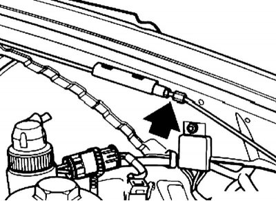
1. Disconnect the wiring connector for the windshield washer nozzle heater and the engine compartment lighting.
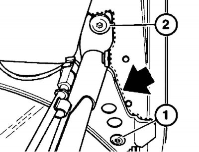
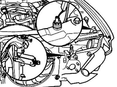
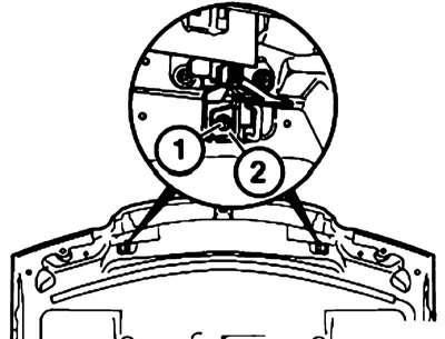
2. Circle the hood hinge) to avoid adjusting it after installation. Remove the bolt (1) and loosen the screw (2).
3. Remove the hood.
4. Installation is carried out in the reverse order. If the hood is aluminum (this is indicated by the holes on its side end), be sure to replace any damaged gaskets between the hinge and the hood.
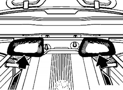
5. Check the air intake boxes on the left and right by making a contact print (for example, using tire mounting paste).
The bonnet seal must be perfect, otherwise water and exhaust gases may penetrate into the car's interior.
6. Installation is carried out in the reverse order, align the outline applied to the hood during removal with the edges of the hinges. A new hood, or a hood without installation marks, should be adjusted as described below.
Adjustment
The clearance values are specified in the Chapter Specifications Body.
1. Adjust the stop screw (1) of the hinge on the right and left to size A = 16±1 mm.
The buffer (2) of the stop screw must not be damaged. Replace the hinge if necessary.
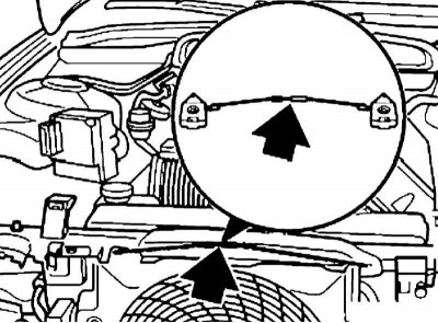
2. Adjust the cable using the adjusting sleeve so that it is not slack, but not too tight. The cable sheath must be completely located in the guide sleeve of the lock.
3. Otherwise, if you pull the hood release handle, the cable will slip in the bushing and the lock will not open. Adjust the cable stroke if necessary.
4. Turn back the stop screw buffers without pushers. If the buffers with pushers are installed, press the pushers into the buffers and turn them slightly to the left in this position with a Phillips screwdriver. This will lock the pushers in the stop screw buffers.
5. Loosen the screws (1 and 2 on illustrations) loops on the left and right.
Do not damage the gasket between the hinge and the hood, replace the gasket if necessary. If the adjustment range is insufficient, you can loosen the hinge mounting bolts to the body and move the hinge.
6. Adjust the position of the hood so that the gap between the wings and its side ends is the same in width along the entire length of the hood. In addition, the gap between the hood and the front wings near the headlights should be uniform. The permissible deviation is 1 mm, i.e. the hood can be shifted back from the front wings by no more than 1 mm. Near the windshield, the hood should smoothly transition into the wings.
7. Tighten the loose bolts.
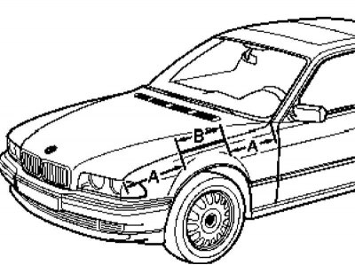
8. To adjust the height of the hood (at the hinges), carefully close it and measure the height of the hood installation on the section (B). Dimension (A) from the corresponding outer edge of the wing (from the headlight or from the windshield) = 200 mm. The bonnet on section (B) must be level with the front fenders. The permissible deviation is 1 mm, i.e. the bonnet may be lower than the fenders by no more than 1 mm.
9. Measure the height of the bonnet installation relative to the front fenders near the windscreen. The bonnet should be 3 mm lower than the front fenders. The permissible deviation is 1 mm, i.e. the bonnet on this section may be located lower than the fenders by no more than 4 mm. This is achieved by correctly setting the gap between the bonnet and the front fenders on section (B).
10. Determine the hood installation height on section (B), measure the deviation value and open the hood. Fix the hood.
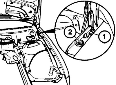
11. Unscrew the bolts (1 and 2) and put or, conversely, remove the required number of shims depending on the deviation. Tighten the loosened bolts on the left and right in turn. Close the hood, check the height and, if necessary, readjust.
12. To adjust the height of the hood (by locks), carefully close the hood and determine its height - the hood and front fenders near the headlights should be at the same height. The permissible deviation is 1 mm, i.e. the hood may be lower than the fenders by no more than 1 mm. Measure the deviation.
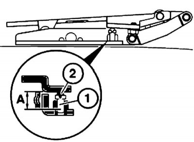
13. Open the hood, unscrew the bolt (1) and remove the striker (2) of the lock.
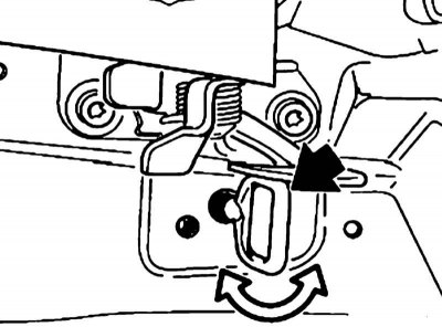
14. Turn the regulator until the deviation is equalized (work is done on the left and right). Reinstall the retainer, close the hood, check its height near the headlights and adjust it if necessary.
15. Measure the distance the front edge of the bonnet projects in front of the top edge of the headlight lens and adjust this distance if necessary.
16. Unscrew the buffers (see illustration) so that the hood fits tightly against them. On the buffers with pushers turn the pushers slightly to the right with a Phillips screwdriver - this will unlock the buffers and move them upward.
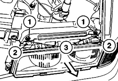
17. To adjust the projection, loosen the nuts (1), loosen the adjusting nuts (3) and move the headlights in the appropriate direction.
The headlights must be installed without tension. If necessary, move the lower adjusting screws (2). Then adjust the headlight angle (see chapter On-board electrical equipment).
18. Check the air intake boxes on the left and right by making a contact print (for example, using tire mounting paste).
The bonnet seal must be perfect, otherwise water and exhaust gases may penetrate into the car's interior.
Removal and installation racks
Because of the risk of injury when performing the following operations, support the hood with suitable means or have an assistant support it.
1. Open the hood.
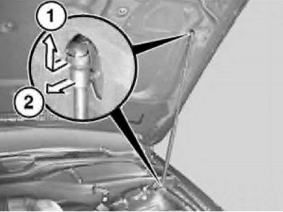
2. Slide the retaining spring to the end of the rod (arrow 1).
3. Disconnect the gas-filled shock absorber from the ball head (arrow 2).
4. Installation is carried out in reverse order.
This article is available at russian, bulgarian, belarusian, ukrainian, serbian, croatian, romanian, polish, slovak, hungarian
Article verified: Polikarpov Saveliy
Share information:
Previous articles
БМВ E38: Exterior
Next articles
Similar articles on other types of BMW cars:
Hood — removal, installation and adjustment BMW 3 Series E46 (1998-2006, petrol)
Mechanical fuel pump — checking, adjustment, removal and installation BMW 3 Series E21 (1975-1983)
Removal, installation and adjustment of the hood BMW 5 Series E28 (1981-1988)
Removal and installation the engine compartment hood cable BMW 5 Series E34 (1988-1996)
Removal and installation the hood BMW X3 E83 (2003-2010)
Hood — removal, installation and adjustment BMW X5 E53 (1999-2006)
Link in different formats to this page
Visitor comments
No comments yet
- General information
- Introduction to guide
- Manual
- Maintenance
- Power unit
- Engine M60/1, M60/2 (petrol)
- M62 engine (petrol)
- M57 engine (diesel)
- M67 engine (diesel)
- Cooling system
- Fuel system (petrol)
- Fuel system (diesel)
- Exhaust system
- Ignition and control systems
- Charge and launch systems
- Transmission
- Clutch
- Mechanical gearbox
- Automatic gearbox
- Cardan and drive shafts
- Chassis
- Brake system
- Front suspension
- Rear suspension
- Steering
- Body
- Exterior
- Interior
- Electrical equipment
- Equipment and devices
- Lighting
- Heating and air conditioning
- Electrical circuits
- General information
- Care and maintenance
- Power unit
- Minor engine repair
- Engine overhaul
- Lubrication system
- Cooling system
- Ignition system
- Supply system
- Injection system (petrol)
- Injection system (diesel)
- Exhaust system
- Transmission
- Clutch
- Manual gearbox
- Automatic gearbox
- Cardan gear
- Rear axle and shafts
- Chassis
- Front suspension
- Rear suspension
- Steering
- Wheels and tires
- Brake system
- Body
- Body elements
- Electrical equipment
- Equipment and devices
- Electrical circuits