
Table of contents: Left cylinder head ↓ Right cylinder head ↓
- Home
- BMW 7 Series
- E38
- Power unit
- M67 engine (diesel)
- Removal and installation cylinder heads
Removal and installation cylinder heads (BMW 7 Series E38)
1. Disconnect the negative cable from the battery.
2. Remove the upper cooling fan cover.
3. Drain the engine cooling system (see chapter Vehicle settings and routine maintenance).
1. Remove the left camshafts and intake manifold (see section Removal and installation the intake manifold).
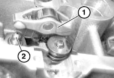
2. Remove the rocker arms (1) and hydraulic compensators (2) of the valve clearances. Make sure that the rocker arm rollers move smoothly.
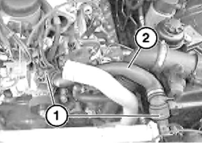
3. Release the water hose (2) from the clamps (1) and move it to the side.
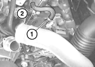
4. Loosen the clamp (1) and disconnect the hose (2).
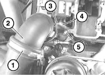
5. Loosen the clamp (1) and disconnect the suction tube (2). Release the pipeline (3) from the holder, disconnect the hose (4), unscrew the bolt (5) and remove the suction tube (2).
6. Unscrew the bolts (1) from the high-pressure fuel pump (3), move the pipeline (2) to the side and remove the high-pressure fuel pump.
7. Remove both bolts on the air duct and remove it.
8. Unscrew the hollow bolts (1) and remove the pressure oil line (2).
9. Remove the guide mounting bolt at the front of the cylinder head.
10. Remove the bolts.
11. Unscrew the bolts (1), disconnect the pressure pipes (2) and remove the fuel distribution line (3).
12. Disconnect the glow plug connectors. Disconnect the wire (1), lift and secure the hose (2) and the engine wiring harness (3).
13. Loosen the clamps (1 and 3) and disconnect the hose (4).
14. Remove the three front cylinder head bolts and then the cylinder head mounting bolts reverse sequences.
15. Remove the cylinder head.
16. If necessary, remove the glow plugs.
17. Remove the cylinder head gasket and clean the mating surfaces and all blind threaded holes in the engine crankcase from engine oil and coolant.
18. If no work has been carried out on the cylinder block that causes a change in the piston bottom protrusion, then it is necessary to use new cylinder head gasket with the same thickness marking as the old gasket. Otherwise, the repair thickness of the sealing gasket should be determined again by measuring the protrusion of the bottom of all pistons relative to the plane of the cylinder block. If the protrusion from 0.92 to 1.03 mm use a gasket with 2-my holes, and when protruding more than 1.03 mm - With 3-my holes.
19. Tighten the cylinder head mounting bolts so that they do not protrude above the mating surface of the cylinder head and carefully install it.
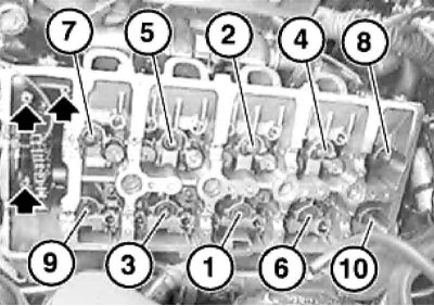
20. Insert all cylinder head mounting bolts and tighten them in the sequence shown on illustrations.
21. Tighten the three front cylinder head bolts.
1. Press the lock (1), disconnect the plug (2) of the diagnostic connector and put it aside.
2. Remove the turbocharger mounting bolts.
3. Remove both right camshafts and the intake manifold (see section Removal and installation the intake manifold).
4. Remove the rocker arms (1) and hydraulic compensators (2) valve clearances. Make sure the rocker arm rollers move smoothly.
5. Remove the three front cylinder head bolts and the cylinder head mounting bolts reverse sequences.
6. Loosen the clamps (1 and 2) and remove the hose (3).
7. Remove the guide mounting bolt at the front of the cylinder head (see illustration).
8. Follow the steps in paragraphs 15 through 21.
2. Remove the upper cooling fan cover.
3. Drain the engine cooling system (see chapter Vehicle settings and routine maintenance).
If the coolant is not completely drained from the cylinder block, it will end up in the engine oil pan when the cylinder head is removed.
Left cylinder head
1. Remove the left camshafts and intake manifold (see section Removal and installation the intake manifold).
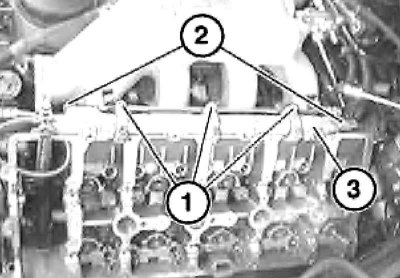
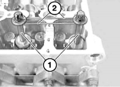
2. Remove the rocker arms (1) and hydraulic compensators (2) of the valve clearances. Make sure that the rocker arm rollers move smoothly.
Rocker arms and hydraulic tappets that have been in use should be installed in their original locations, so when removing them, arrange them accordingly.
3. Release the water hose (2) from the clamps (1) and move it to the side.
4. Loosen the clamp (1) and disconnect the hose (2).
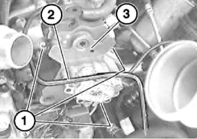
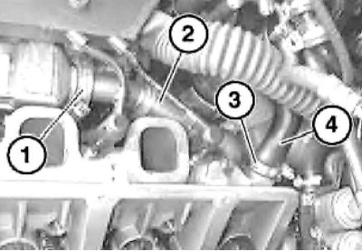
5. Loosen the clamp (1) and disconnect the suction tube (2). Release the pipeline (3) from the holder, disconnect the hose (4), unscrew the bolt (5) and remove the suction tube (2).
6. Unscrew the bolts (1) from the high-pressure fuel pump (3), move the pipeline (2) to the side and remove the high-pressure fuel pump.
When installing, replace the sealing ring under the injection pump gear if necessary.
7. Remove both bolts on the air duct and remove it.
During installation, replace the sealing ring at the end of the air duct if necessary.
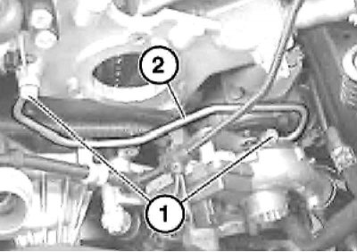
8. Unscrew the hollow bolts (1) and remove the pressure oil line (2).
Replace bolt seals when installing.
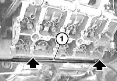
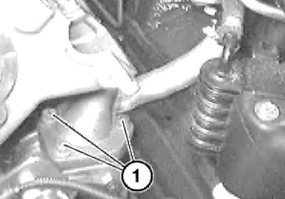
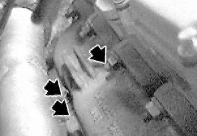
9. Remove the guide mounting bolt at the front of the cylinder head.
Use new fasteners when installing.
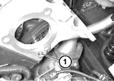
10. Remove the bolts.
When installing, clean the mating surfaces and replace the flange joint gasket.
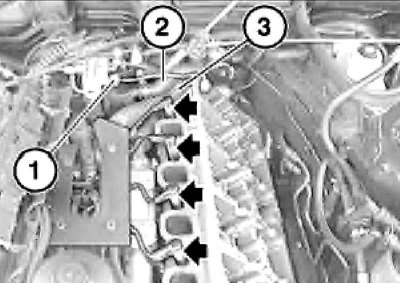
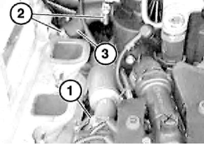
11. Unscrew the bolts (1), disconnect the pressure pipes (2) and remove the fuel distribution line (3).
12. Disconnect the glow plug connectors. Disconnect the wire (1), lift and secure the hose (2) and the engine wiring harness (3).
13. Loosen the clamps (1 and 3) and disconnect the hose (4).
Do not remove the EGR pipe.
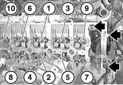
14. Remove the three front cylinder head bolts and then the cylinder head mounting bolts reverse sequences.
Cylinder head bolts No.7-10 and No.1-6 have different diameters (M10 and M12). Reusing cylinder head bolts is not permitted. Do not completely remove bolt No.10 to remove the cylinder head.
15. Remove the cylinder head.
The glow plugs protrude above the lower plane of the cylinder head, do not damage them, and do not scratch the mating surfaces of the head.
16. If necessary, remove the glow plugs.
17. Remove the cylinder head gasket and clean the mating surfaces and all blind threaded holes in the engine crankcase from engine oil and coolant.
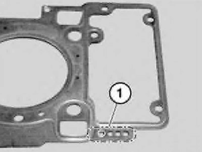
Pay attention to the number of holes in the cylinder head gasket. Make sure that no sealing material remains in the oil and coolant supply channels.
18. If no work has been carried out on the cylinder block that causes a change in the piston bottom protrusion, then it is necessary to use new cylinder head gasket with the same thickness marking as the old gasket. Otherwise, the repair thickness of the sealing gasket should be determined again by measuring the protrusion of the bottom of all pistons relative to the plane of the cylinder block. If the protrusion from 0.92 to 1.03 mm use a gasket with 2-my holes, and when protruding more than 1.03 mm - With 3-my holes.
19. Tighten the cylinder head mounting bolts so that they do not protrude above the mating surface of the cylinder head and carefully install it.
20. Insert all cylinder head mounting bolts and tighten them in the sequence shown on illustrations.
Cylinder head mounting bolts No.7-10 and No.1-6 differ in diameter (M10 and M12).
21. Tighten the three front cylinder head bolts.
Right cylinder head
If the installed boost air hoses are not degreased and are damp, this may lead to turbocharger failure.
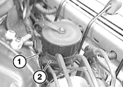
1. Press the lock (1), disconnect the plug (2) of the diagnostic connector and put it aside.
2. Remove the turbocharger mounting bolts.
When installing, clean the mating surfaces and replace the turbocharger gasket.
3. Remove both right camshafts and the intake manifold (see section Removal and installation the intake manifold).
4. Remove the rocker arms (1) and hydraulic compensators (2) valve clearances. Make sure the rocker arm rollers move smoothly.
Rocker arms and hydraulic tappets that have been in use should be installed in their original locations, so when removing them, arrange them accordingly.
5. Remove the three front cylinder head bolts and the cylinder head mounting bolts reverse sequences.
Cylinder head mounting bolts #7-10 and #1-6 differ in diameter. Do not completely unscrew bolt #10 to remove the cylinder head. Reusing bolts is not permitted.
6. Loosen the clamps (1 and 2) and remove the hose (3).
7. Remove the guide mounting bolt at the front of the cylinder head (see illustration).
Use new fasteners when installing.
8. Follow the steps in paragraphs 15 through 21.
This article is available at russian, bulgarian, belarusian, ukrainian, serbian, croatian, romanian, polish, slovak, hungarian
Article verified: Polikarpov Saveliy
Share information:
Previous articles
БМВ E38: M67 engine (diesel)
Next articles
Similar articles on other types of BMW cars:
Removal and installation the wheel cylinder BMW 3 Series E21 (1975-1983)
Removal and installation the cylinder head BMW 3 Series E30 (1982-1994)
Removal and installation the clutch master cylinder BMW 5 Series E12 (1972-1981)
Removal and installation of cylinder head — engines M20, M21, M30 BMW 5 Series E34 (1988-1996)
Removal and installation the clutch master cylinder BMW X3 E83 (2003-2010)
Removal and installation the lock cylinder BMW X5 E53 (1999-2006)
Link in different formats to this page
Visitor comments
No comments yet
- General information
- Introduction to guide
- Manual
- Maintenance
- Power unit
- Engine M60/1, M60/2 (petrol)
- M62 engine (petrol)
- M57 engine (diesel)
- M67 engine (diesel)
- Cooling system
- Fuel system (petrol)
- Fuel system (diesel)
- Exhaust system
- Ignition and control systems
- Charge and launch systems
- Transmission
- Clutch
- Mechanical gearbox
- Automatic gearbox
- Cardan and drive shafts
- Chassis
- Brake system
- Front suspension
- Rear suspension
- Steering
- Body
- Exterior
- Interior
- Electrical equipment
- Equipment and devices
- Lighting
- Heating and air conditioning
- Electrical circuits
- General information
- Care and maintenance
- Power unit
- Minor engine repair
- Engine overhaul
- Lubrication system
- Cooling system
- Ignition system
- Supply system
- Injection system (petrol)
- Injection system (diesel)
- Exhaust system
- Transmission
- Clutch
- Manual gearbox
- Automatic gearbox
- Cardan gear
- Rear axle and shafts
- Chassis
- Front suspension
- Rear suspension
- Steering
- Wheels and tires
- Brake system
- Body
- Body elements
- Electrical equipment
- Equipment and devices
- Electrical circuits