
Attention! Protect the generator from contamination. After disconnecting the pipes and hoses, close the resulting holes with special caps.
The position of the high-pressure fuel pump relative to the valve mechanism is arbitrary and does not affect the operation of the engine.
The replacement of the high-pressure fuel pump must be carried out in the following order. Prepare the tools "13.5.020", "13.5.191" and "13.5.192". Remove the intake manifold, fan shroud, and front auxiliary engine protection panel.
Drain the coolant (only from the radiator of the engine cooling system) and the plastic return tube. Remove the alternator drive belt.
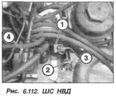
Disconnect the SS (1, Fig. 6.112) from the high-pressure fuel pump. Loosen the clamps of the fuel supply line (2) and disconnect the return fuel hose (3) from the high-pressure fuel pump. Using the "13.5.020" tool, unscrew the union nut (4) of the high-pressure line.
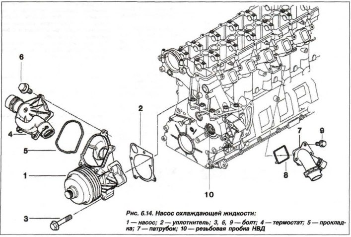
Unscrew the screw plug (10, see Fig. 6.14) access to the nut securing the high-pressure fuel pump drive sprocket.
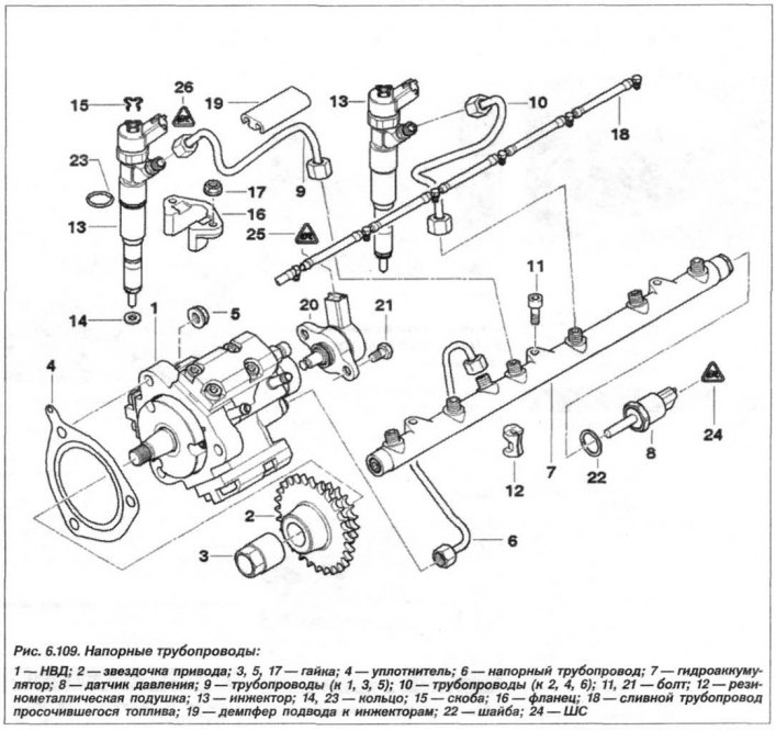
Unscrew the nut (3, see Fig. 6.109) fastenings of the high-pressure fuel injection sprocket.
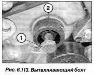
Screw the device "13.5.192" into the timing belt cover. Screw the device "13.5.191" by hand (2, Fig. 6.113), without the ejector bolt (1), into the high-pressure fuel pump sprocket. Screw in the ejector bolt (1) until it fits snugly against the high-pressure fuel pump.
Unscrew the nuts (5, see Fig. 6.109) fastening the high-pressure fuel pump. Tighten the ejector bolt (1) until the high-pressure fuel pump separates from the sprocket. Remove the high-pressure fuel pump.
Attention! To ensure subsequent installation of the high-pressure fuel pump, the "13.5.190" device with the drive sprocket must be left on the engine and the ejector bolt must be unscrewed.
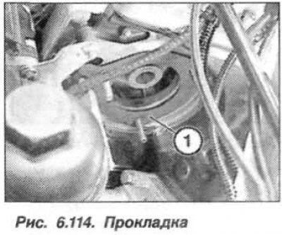
The installation of the HPF should be carried out in the reverse order, while it is necessary to replace the sealing gasket (1, Fig. 6.114), paying attention to the correctness of its position.
The surfaces to be sealed must be dry and free from grease.
Tighten the M14x1.5 nut securing the high-pressure fuel pump drive sprocket to a torque of 65 N·m (6.5 kgf·m). Replace the sealing ring, lightly lubricate it with engine oil and tighten the M30x1.0 threaded plug to a torque of 70 N·m (7.0 kgf·m). Tighten the union nuts on the hydraulic accumulator and high-pressure fuel pump to a torque of 23 N·m (2.3 kgf·m).
Pay attention to the position of the rubber-metal cushion (19, see Fig. 6.109) under the pressure pipes. Replace the clamps of the fuel hoses of the high-pressure fuel pump and assemble the engine. To remove air from the fuel system, turn on the ignition for about 1 minute.