
Prepare tools "12.1.301" and "12.7.050". Read information from the fault memory of the ECU KSUD (DME). Remove the sound-absorbing casing of the ignition coils. Open the control electronics compartment.
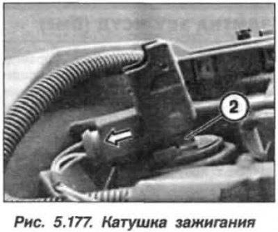
Open the retainer and disconnect the shock absorber (1, Fig. 5.177) coils in the direction indicated by the arrow. Pull the ignition coil (2) up slightly and perform similar actions on all rod ignition coils.
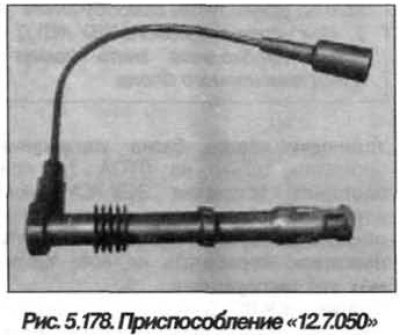
Install the device "12.7.050" (1, Fig. 5.178) between the spark plug and the ignition coil.
Further actions should be performed in accordance with the Manual for the DIS system.
Note: The ignition signal is multi-spark, its shape is shown in Figure 5.179.
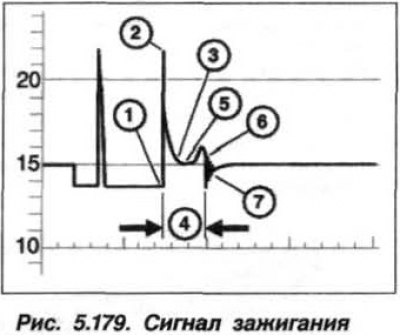
The multi-spark ignition signal has the following characteristics:
- (1), beginning of the breakout;
- (2), the height of the ignition voltage amplitude;
- (3), the magnitude of the spark formation voltage;
- (4), spark discharge duration;
- (5), voltage curve on spark plug electrodes;
- (6), the beginning of the process of damping of oscillations;
- (7), the process of oscillation damping.
Note: The voltage pulse value on the oscillogram is approximately 20–25% lower than its actual value.
What is important is not the height of the voltage pulse, but the uniformity of operation of all cylinders.
(The original article is posted on the resource «bmwman»)