
Table of contents: RK type "NV125/LWX-500" ↓ RK type "ATS 500" ↓
- Home
- BMW X5
- E53
- Transmission
- Transfer case and cardan
- Replacing the output flange seal of the RK
Replacing the output flange seal of the RK (BMW X5 E53)
RK type "NV125/LWX-500"
Technology for replacing the seal of the outlet flange of the RK type "NV125/LWX-500" for the rear drive, the technology for replacing the transfer case axle shaft seal and the transfer case input flange seal of the ATC 500 type is similar. In this case, the transfer case may not be removed, but it is necessary to remove the exhaust system and disconnect the cardan shaft from the transfer case.
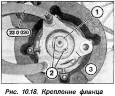
The flange should be fixed first (3, Fig. 10.18) with the device "23.0.020" and, using the device "23.2.320", unscrew the nut (1).
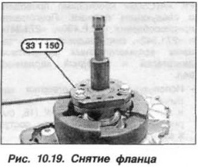
When tightening the bolt on the device "33.1.150", (fig. 10.19) remove the flange and take it off to gain access to the gland. Remove the gland using the "23.0.490" tool, having first made a hole in the gland using a punch.
The new seal is pressed in using the "27.1.380" tool flush into the crankcase hole.
Nut (1, see Fig. 10.18) replace the flange fasteners, apply a sealant such as "Loctite 270" or "Hilogrip". Screw the flange until it stops and tighten its fastening nut to a torque of 110 N·m (11.0 kgf·m) for the "NV125" type RK and to a torque of 300.0 N·m (30.0 kgf·m) for the "LWX500" type RK. Lock the nut (1) by punching at the points (2, see Fig. 10.18).
Upon completion of the work, check the oil level in the transfer case and, if necessary, restore it. Check the tightness of the unit.
RK type "ATS 500"
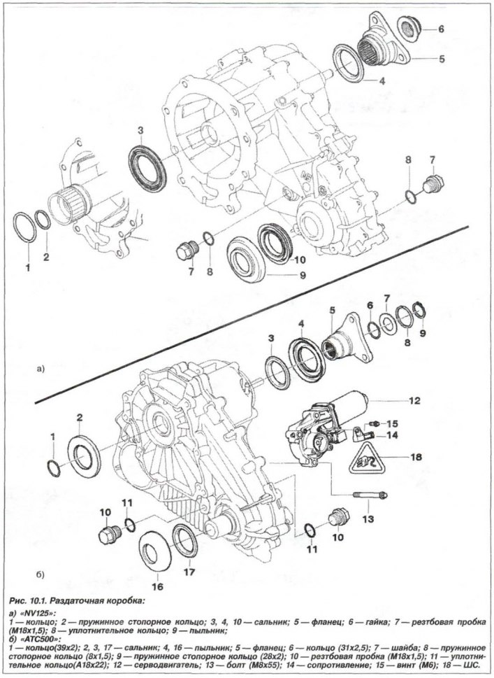
The technology for replacing the output flange seal of the RK type "ATS 500" on the rear drive is similar to the technology for replacing the RK type seal "NV125/LWX-500". In this case, it is necessary to prepare the equipment "23.0.490", "27.1.400" and "33.1.150", remove the RK and the retaining ring (8, see Fig. 10.1,b).
Using the "33.1.150" device, unscrew the flange. Make a hole in the seal with a center punch, install the "23.0.490" device and knock the seal out of the transfer case.
Replace the ring before installing the seal (6, see Fig. 10.1,b) round section (31x2.5) flange and make sure it is installed correctly.
The installation of a new oil seal should be carried out using the "27.1.400" mandrel.
Caution! When installing the flange, the shaft may shift and then it will not be possible to install the retaining ring.
When installing a flange on an output shaft with a mounting groove (1, Fig. 10.20) follows:
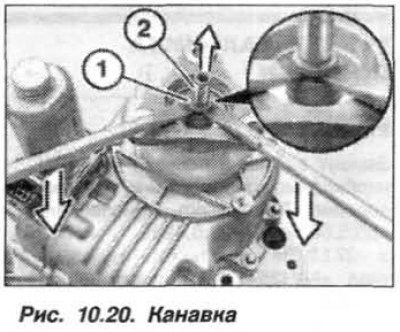
- install flange;
- using two mounting blades (3), press the flange downwards or the output shaft (2) upwards until the groove for the retaining ring is fully visible;
- install the retaining ring.
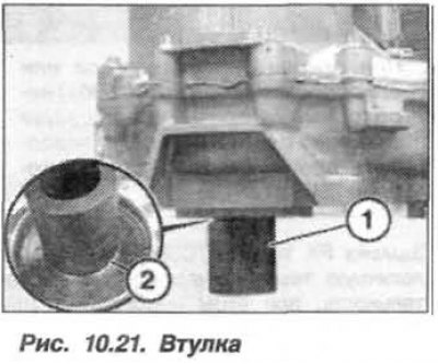
When installing a flange on an output shaft without a mounting groove, the transfer case should be supported by placing it under the input shaft (2, Fig. 10.21) suitable sleeve (1).
Upon completion of the work, check the oil level in the transfer case and, if necessary, restore it. Check the tightness of the unit.
(The original article is available on the website: BMWMAN.ru)
This article is available at russian, bulgarian, belarusian, ukrainian, serbian, croatian, romanian, polish, slovak, hungarian
Article verified: Zhuravleva Isolda
Share information:
Previous articles
БМВ E53: Transfer case and cardan
Next articles
Similar articles on other types of BMW cars:
Replacing the front crankshaft oil seal and intermediate shaft oil… BMW 3 Series E21 (1975-1983)
Replacing the rear crankshaft oil seal BMW 5 Series E28 (1981-1988)
Replacing the coolant BMW 5 Series E12 (1972-1981)
Pinion Shaft Flange Seal — Replacement BMW 7 Series E32 (1986-1994)
Replacing the cabin filter (ventilation system) BMW 7 Series E38 (1994-2001)
Input link flange seal (ATS 400/500 XDRIVE) BMW X3 E83 (2003-2010)
Link in different formats to this page
Visitor comments
No comments yet
- General information
- Manual
- Maintenance
- M54 petrol engine
- Engine repair
- Lubrication system
- Cooling system
- Supply system
- Injection system
- Exhaust system
- Engine electrics
- M62 petrol engine
- Engine repair
- Lubrication system
- Cooling system
- Supply system
- Exhaust system
- Engine electrics
- N62 petrol engine
- Engine repair
- Cooling and lubrication system
- Power and exhaust system
- Engine electrics
- Diesel engine M57
- Engine repair
- Lubrication system
- Cooling system
- Power and exhaust system
- Engine electrics
- Turbocharging system
- Transmission
- Clutch
- Mechanical gearbox
- Automatic gearbox
- Transfer case and cardan
- Chassis
- Brake system
- Steering
- Front suspension
- Rear suspension
- Wheels and tires
- Body
- Exterior
- Interior
- Doors and windows
- Repair and maintenance
- Heater and air conditioner
- Electrical equipment
- Equipment and devices
- Levers and switches
- Electrical circuits