
Table of contents: Car with automatic transmission ↓ A car equipped with a manual…↓
- Home
- BMW X5
- E53
- Transmission
- Transfer case and cardan
- Transfer case replacement
Transfer case replacement (BMW X5 E53)
Car with automatic transmission
Removal of the transfer case in combination with the automatic transmission must be carried out in the following order.
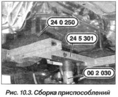
Prepare the equipment "00.2.030", "24.0.250", "27.1.100", "24.5.301" and "27.1.100".
Set the automatic transmission selector lever to position "P", remove the exhaust system, stiffening plate and protective panels of the engine compartment.
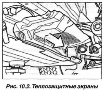
Remove the heat shields (Fig. 10.2) and disconnect the oxygen sensor wires from the clamps.
Disconnect the front anti-roll bar, rear heat shield, remove the front propeller shaft and drain the oil from the transfer case.
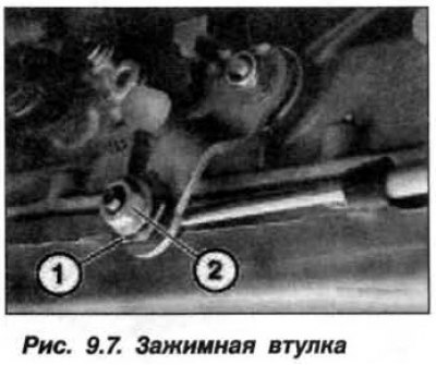
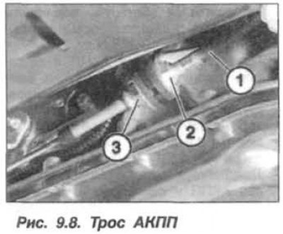
Disconnect the automatic transmission control cable and remove it from the bracket (see Fig. 9.7 and Fig. 9.8). Disconnect the ventilation pipe.
 |
 |
Support the automatic transmission using the assembly of devices - "00.2.030" and "24.5.301" and "24.0.250" (Fig. 10.3) for the automatic transmission "A5S440Z" (5HP24). For automatic transmission "A5S360R" ("GM5") – use the device "24.5.305" instead of "24.0.250"
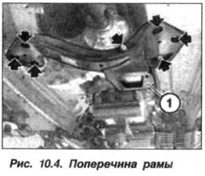
Loosen the bolts (7 pcs., arrows, Fig. 10.4) and remove the cross member (1) of the frame. Disconnect the ventilation pipe from the transfer case and release the wires from the clamps on the transfer case.
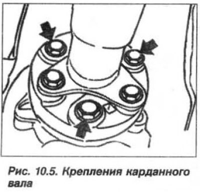
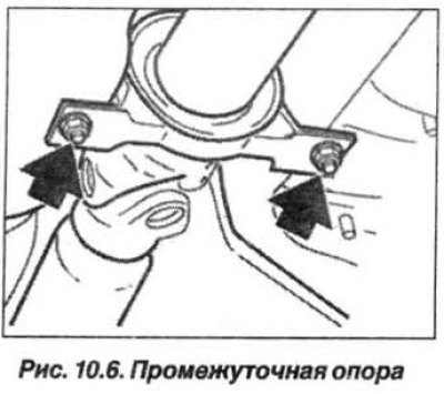
Loosen the bolts (arrows, Fig. 10.5) cardan shaft fasteners and nuts (arrows, Fig. 10.6) intermediate support.
 |
 |
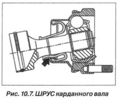
Attention! Avoid falling of the cardan shaft. This can lead to damage of the joints and rubber cuff of the CV joint (arrow, Fig. 10.7).
Lightly press the intermediate support of the cardan shaft downwards and remove the shaft from the flange of the secondary (output) shaft of the automatic transmission. Move the cardan shaft to the side and secure it with a wire clamp to the car body.
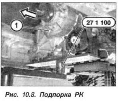
Support the transfer case with devices "27.1.100" and "00.2.030" (Fig. 10.8).
Unscrew the bolts securing the RC to the automatic transmission and remove the RC.
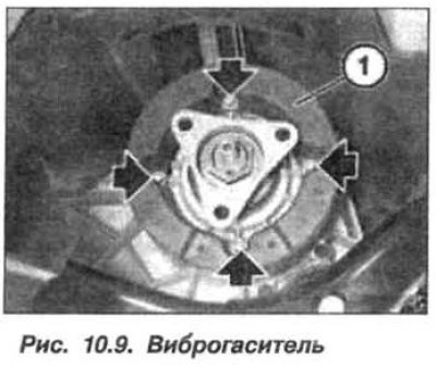
In case of installing a new RK, it is necessary to unscrew the screws (2, Fig. 10.9) and move the vibration damper (1) onto it.
The installation of the RK should be carried out in the reverse order, and it is necessary to:
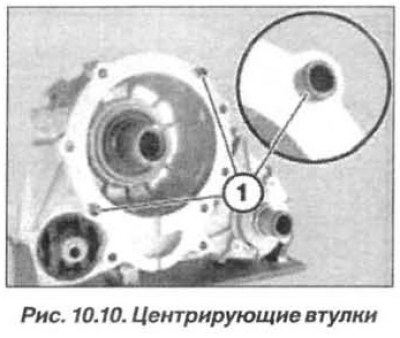
- check the position and technical condition of the centering bushings (1, Fig. 10.10), replace damaged elements if necessary;
- lightly lubricate the gear rims (grease "Weicon Antisize");
- check the rubber pads of the transfer case mount;
- when installing, the intermediate support must be at a strictly right angle (90°) to the cardan shaft;
- tighten the intermediate support nuts to a torque of 21 N·m (2.1 kgf·m);
- replace the self-locking nuts of the cardan shaft;
- when installing the cardan shaft, hold the bolt from turning with a wrench, turn only the nut. Tightening torque of the M12 (10.9) nut is 100.0 N·m (10.0 kgf·m);
- tighten the M10 bolts securing the transfer case to the automatic transmission to a torque of 41 N·m (4.1 kgf·m);
- tighten the M12 bolts securing the transfer case to the cross frame to a torque of 74 N·m (7.4 kgf·m);
- tighten the M12 bolts securing the cross frame to the vehicle body to a torque of 74 N·m (7.4 kgf·m);
- tighten the M10 bolts securing the cross frame to the vehicle body to a torque of 41 N·m (4.1 kgf·m);
- tighten the automatic transmission control cable mounting nut to a torque of 15 N·m (1.5 kgf·m);
- pour oil into the transfer case and check its level, which should be up to the lower edge of the filler plug (fig. 10.11);
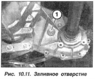
- add oil through the filler hole, replacing the gasket, tighten the M18 plug to a torque of 33 N·m (3.3 kgf·m).
- install the stiffening plate.
Attention! When replacing the servomotor or its resistance ("ATC500"), it is necessary to erase the previous resistance value and perform programming using the "DIS-stand".
The replacement of the transfer case of the "ATC500" type has a similar technological sequence, however, it is necessary to take into account the following features:
- when removing the RK, it is necessary to disconnect the shock absorbers (1 and 2, Fig. 10.12), unscrew the screw (3) and remove the servomotor resistance of the RK;
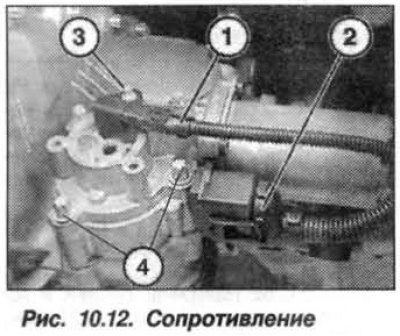
- to remove the servomotor, unscrew the bolt (4) and remove it from the RK;
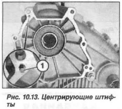
- before installation, it is necessary to check the centering pins (1, Fig. 10.13), if necessary, replace them and apply a light layer of grease such as "Weicon Antisize".
The bolt tightening should be as follows:
- tighten the M10 bolts securing the transfer case crossmember to the body to a torque of 41 N·m (4.1 kgf·m);
- tighten the M12 bolts securing the frame crossmember to the transfer case to a torque of 74 N·m (7.4 kgf·m);
- tighten the M6 screw for fastening the resistor to the servomotor with a torque of 5.0 N·m (0.5 kgf·m);
- tighten the M8 bolt securing the servomotor to the transfer case to a torque of 22 N·m (2.2 kgf·m).
A car equipped with a manual transmission
Replacing the transfer case, in combination with the manual transmission, has a similar technological sequence, while for its support the devices "00.2.030" and "23.0.130" are used.
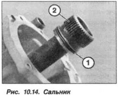
Replace the seal when installing (1, Fig. 10.14) drive shaft (2) RK.
The bolt tightening should be as follows:
- bolt M12 (10.9) of the flexible coupling of the cardan shaft should be held from turning with a wrench, only the nut should be turned. Tightening torque of the nut is 55.0 N·m (5.5 kgf·m) with an additional turn of 90°. Tighten bolts M10 (8.8) to a torque of 48 N·m (4.8 kgf·m). Tighten bolts M10 (10.9) to a torque of 64 N·m (6.4 kgf·m);
- tighten the M10 (8.8) bolts securing the transfer case to the body to a torque of 41 N·m (4.1 kgf·m);
- tighten the M12 bolts securing the frame crossmember to the vehicle body to a torque of 74 N·m (7.4 kgf·m).
[The article was copied from an online resource: «bmwman»]
This article is available at russian, bulgarian, belarusian, ukrainian, serbian, croatian, romanian, polish, slovak, hungarian
Article verified: Zhuravleva Isolda
Share information:
Previous articles
БМВ E53: Transfer case and cardan
Next articles
Similar articles on other types of BMW cars:
Replacement of decorative moldings BMW 3 Series E30 (1982-1994)
Filter replacement BMW 3 Series E36 (1990-2000)
Engine suspension cushion replacement BMW 5 Series E12 (1972-1981)
Ski Carrying Case BMW 5 Series E34 (1988-1996)
Filter replacement BMW 7 Series E32 (1986-1994)
Changing and topping up oil in the transfer case (ATS 400/500 XDRIVE) BMW X3 E83 (2003-2010)
Link in different formats to this page
Visitor comments
No comments yet
- General information
- Manual
- Maintenance
- M54 petrol engine
- Engine repair
- Lubrication system
- Cooling system
- Supply system
- Injection system
- Exhaust system
- Engine electrics
- M62 petrol engine
- Engine repair
- Lubrication system
- Cooling system
- Supply system
- Exhaust system
- Engine electrics
- N62 petrol engine
- Engine repair
- Cooling and lubrication system
- Power and exhaust system
- Engine electrics
- Diesel engine M57
- Engine repair
- Lubrication system
- Cooling system
- Power and exhaust system
- Engine electrics
- Turbocharging system
- Transmission
- Clutch
- Mechanical gearbox
- Automatic gearbox
- Transfer case and cardan
- Chassis
- Brake system
- Steering
- Front suspension
- Rear suspension
- Wheels and tires
- Body
- Exterior
- Interior
- Doors and windows
- Repair and maintenance
- Heater and air conditioner
- Electrical equipment
- Equipment and devices
- Levers and switches
- Electrical circuits