
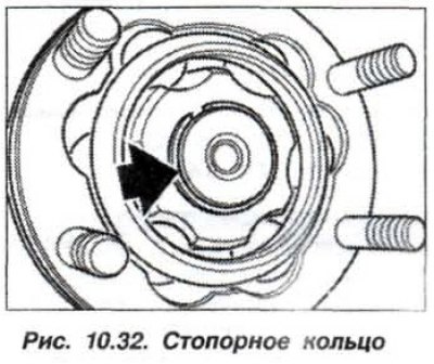
Prepare the equipment "23.1.040", "24.1.040", "26.1.070" and "26.1.110". Remove the propeller shaft assembly and the retaining ring (arrow, Fig. 10.32).
Knock out the bolts (13, see Fig. 10.25) and remove the lining plates (14).
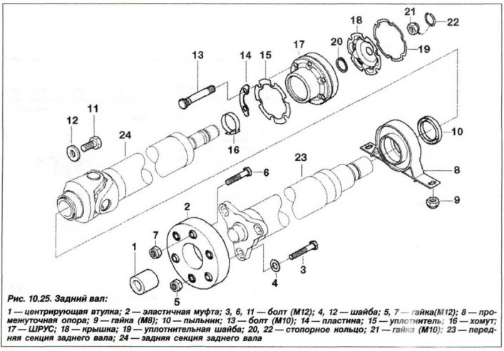
Pull off the protective cover from the CV joint and its sealing gasket (19).
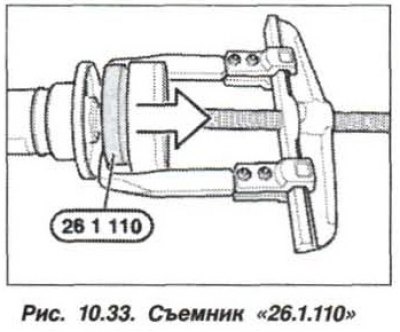
Using puller "26.1.070" or "26.1.110" (fig. 10.33), remove the CV joint.
The installation of the CV joint should be carried out in the reverse order, while it is necessary.
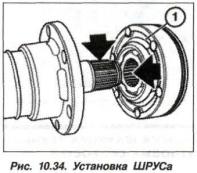
Install the CV joint and, using the mandrel "23.1.040" or "24.1.040", push it until it stops. In this case, the sample (1, Fig. 10.34) under the sealing washer should be facing the protective cover. The splined connection (arrows) of the CV joint and the flange of the GP shaft should be degreased and a thin layer of sealant such as "Loctite 648".
Attention! Make sure that the sealant does not get on the CV joint ball raceway.
Install a new washer (19, see Fig. 10.25) on the CV joint. Apply fresh grease such as Olistamoly 2LN 584/LO to the CV joint cavities on the side of the corrugated boot and the flange of the main gear drive pinion.
Ensure that the lining plates (14) are installed under the CV joint mounting bolts and install a new retaining ring.