
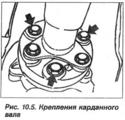
Hold the cardan shaft from turning with a band clamp, unscrew the mounting bolts (arrows, see Fig. 10.5) and remove the cardan joint flange from the flexible coupling. Secure the front section of the rear drive shaft to the vehicle body with a wire clip.
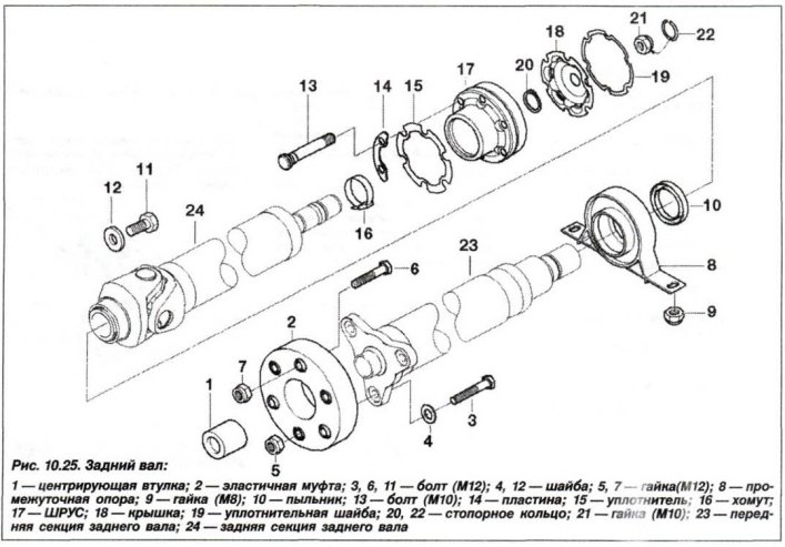
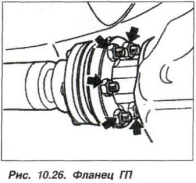
Unscrew the nuts securing the CV joint of the rear section of the propeller shaft from the flange of the main gear (MT) of the rear axle (arrows, Fig. 10.26). Place a screwdriver in the grooves and press the CV joint away from the rear axle flange.
Secure the rear section of the shaft to the car body with a wire clip. Cover the CV joint with a cover to protect it from dirt.
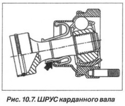
Attention! Do not allow the cardan shaft to fall, due to the possibility of damage, primarily to the CV joint cuff (arrow, see Fig. 10.7).
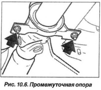
Secure the central bearing with a support and unscrew the nuts securing the intermediate support bearing (arrow, see Fig. 10.6) to the car body.
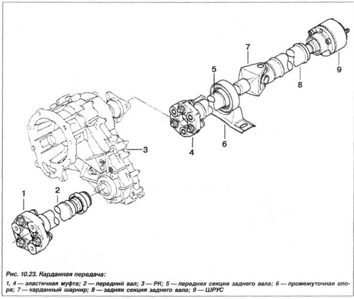
Sink the cardan shaft in the area of the support bearing (6, see Fig. 10.23) down and pull it out of the centering element of the RK flange. Remove the cardan shaft from the car body.
The installation of the rear wheel drive cardan shaft should be carried out in the reverse order, while it is necessary.
The cardan shaft is balanced as an assembly and can only be replaced as a whole. Before installation, the assembly is subject to balancing and checking the condition of the joints at a service station.
Add grease such as Olistamoly 2LN 584/LO to the CV joint cavity. Pull the CV joint out to the stop (1, Fig. 10.27).
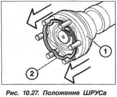
Attention! It is strictly forbidden to push back, (towards the engine) CV joint during assembly, since the grease can squeeze out the sealing ring and damage the CV joint.
Degrease the sealing surfaces of the CV joint and the flange of the drive pinion of the GP. Replace the sealing gasket (2) and fit the cardan shaft with the extended CV joint onto the flange of the drive pinion of the GP. Install new self-locking nuts.
Alternately tighten any two opposite nuts to evenly insert the CV joint into the flange of the drive gear. Tighten these nuts to the torque specified below. Tighten the remaining nuts to the torque:
- flat (M10) 64 Nm (6.4 kgf·m);
- ribbed (M8) 43 Nm (4.3 kgf·m);
- ribbed (M10) 70 Nm (7.0 kgf·m).
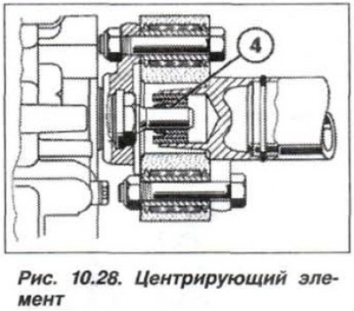
Check the centering element (4, Fig. 10.28), replace the damaged element. Lubricate the centering element with grease such as "Molykote Longterm 2PLUS" or "Optimjl Olistamoly 2".
Tighten the new intermediate support mounting nuts to a torque of 21 N·m (2.1 kgf·m).
Tighten the new self-locking nuts of the bolts securing the elastic coupling to the cardan shaft and to the output flange of the transfer case to the following torque:
- M10 (8.8) 48 Nm (4.8 kgf·m);
- M10 (10.9) 64 Nm (6.4 kgf·m);
- M12 (10.9) 100 Nm (10.0 kgf·m).