
Table of contents: Power supply system diagram ↓ Safety and cleanliness precautions…↓
- Home
- BMW 7 Series
- E38
- Power unit
- Fuel system (petrol)
- General information and safety precautions
General information and safety precautions (BMW 7 Series E38)
The fuel system includes a saddle-shaped fuel tank installed in the rear of the vehicle, a charcoal fuel vapor absorber, fuel lines, an electric fuel pump (on diesel models - an additional high-pressure fuel pump), and an electronic distributed sequential fuel injection system controlled by the electronic engine control unit (ECM). The pressure in the fuel system is maintained by a pressure regulator.
1 - Fuel tank
2 - Electric fuel pump
3 — Fuel pump mounting collar
4 - Suction jet pump
5 — Pressure limiting valve
6 - Drain safety valve
7 — Refueling ventilation pipe
8 — Check valve
9 — Filler neck tube
10 — Filler cap
11 — Fuel tank equalizing line
12, 13 — Working ventilation ducts
14 — Tank
15 — Curtain valve
16 — Vapor discharge pipe
17 — Return fuel line
18 — Fuel supply line
19 — Fuel filter
20 — Pressure regulator
21 - Two-position three-way valve
22 — Distribution main
23 — Outside air supply pipeline
24 — Engine control unit
25 — EVAP valve
26 — Suction pipe
27 - Carbon absorber
The fuel pump is installed in a special holder in the right part of the fuel tank, which ensures uninterrupted fuel supply to the pump in all modes and conditions of vehicle operation. Fuel is supplied to the holder by a suction jet pump installed in the holder support. The suction jet pump, built into the equalizing line of the fuel tank, supplies fuel to the holder from the left part of the fuel tank. Both jet pumps are driven by the return fuel line, and the pressure required for the operation of the suction jet pumps is regulated by a pressure limiting valve. The return fuel line is protected by a special valve, which closes if the pressure drops due to damage or disconnection of the return fuel line. This prevents fuel from leaking out of the fuel tank, for example, when the vehicle is turned over or tilted.
The check valve prevents fuel from splashing back into the filler neck after the fuel nozzle is disconnected.
On petrol models fuel is supplied by the fuel electric pump through the fuel supply line and the fuel filter into the distribution line. On models with an engine M52TU fuel is fed back to the fuel tank through a pressure regulator and a return fuel line attached to the fuel distribution line. On models with an engine M73 the fuel is returned to the fuel tank via a two-position three-way valve, a pressure regulator and a return fuel line. This engine fuel circuit with return from the distribution line is switched on to start the engine and remains switched on for less than 1 minute. After this phase, the two-position three-way valve closes the return fuel line from the distribution line. At the same time, the branch line to the pressure regulator directly on the fuel filter is activated by the same valve. Fuel cannot return from the distribution line. On models with an engine M62TU the pressure regulator and fuel filter are combined into one unit, the distribution line has no shut-off valves and the fuel goes directly from the fuel filter/pressure regulator unit back into the fuel tank.
On diesel models, an electric fuel pump supplies fuel from the fuel tank to the engine. Two types of high-pressure pumps (HPFP) are used for injection into the cylinders: a distribution HPFP (delivers fuel directly to the injector of each cylinder) and injection pump for Common Rail system (creates the necessary pressure in the distribution line for all injectors). In Common Rail systems, another pump is installed between the high-pressure fuel pump and the electric fuel pump – a main pump (M57) or gear pump (M67) – which, when fuel consumption is high, maintains the operation of the fuel pump in the fuel tank.
The fuel level is measured in each part of the fuel tank using a lever sensor. The right sensor is built into the fuel supply unit; the left sensor is located in the left sensor unit. Taking into account the obtained values of electrical resistance of the left and right lever sensors gives the actual filling level of the fuel tank.
Driving style has a significant impact on fuel consumption. Below are some tips on how to save gasoline.
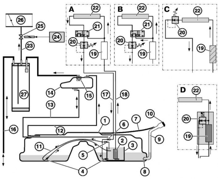
Power supply system diagram
1 - Fuel tank
2 - Electric fuel pump
3 — Fuel pump mounting collar
4 - Suction jet pump
5 — Pressure limiting valve
6 - Drain safety valve
7 — Refueling ventilation pipe
8 — Check valve
9 — Filler neck tube
10 — Filler cap
11 — Fuel tank equalizing line
12, 13 — Working ventilation ducts
14 — Tank
15 — Curtain valve
16 — Vapor discharge pipe
17 — Return fuel line
18 — Fuel supply line
19 — Fuel filter
20 — Pressure regulator
21 - Two-position three-way valve
22 — Distribution main
23 — Outside air supply pipeline
24 — Engine control unit
25 — EVAP valve
26 — Suction pipe
27 - Carbon absorber
The fuel pump is installed in a special holder in the right part of the fuel tank, which ensures uninterrupted fuel supply to the pump in all modes and conditions of vehicle operation. Fuel is supplied to the holder by a suction jet pump installed in the holder support. The suction jet pump, built into the equalizing line of the fuel tank, supplies fuel to the holder from the left part of the fuel tank. Both jet pumps are driven by the return fuel line, and the pressure required for the operation of the suction jet pumps is regulated by a pressure limiting valve. The return fuel line is protected by a special valve, which closes if the pressure drops due to damage or disconnection of the return fuel line. This prevents fuel from leaking out of the fuel tank, for example, when the vehicle is turned over or tilted.
The check valve prevents fuel from splashing back into the filler neck after the fuel nozzle is disconnected.
On petrol models fuel is supplied by the fuel electric pump through the fuel supply line and the fuel filter into the distribution line. On models with an engine M52TU fuel is fed back to the fuel tank through a pressure regulator and a return fuel line attached to the fuel distribution line. On models with an engine M73 the fuel is returned to the fuel tank via a two-position three-way valve, a pressure regulator and a return fuel line. This engine fuel circuit with return from the distribution line is switched on to start the engine and remains switched on for less than 1 minute. After this phase, the two-position three-way valve closes the return fuel line from the distribution line. At the same time, the branch line to the pressure regulator directly on the fuel filter is activated by the same valve. Fuel cannot return from the distribution line. On models with an engine M62TU the pressure regulator and fuel filter are combined into one unit, the distribution line has no shut-off valves and the fuel goes directly from the fuel filter/pressure regulator unit back into the fuel tank.
On diesel models, an electric fuel pump supplies fuel from the fuel tank to the engine. Two types of high-pressure pumps (HPFP) are used for injection into the cylinders: a distribution HPFP (delivers fuel directly to the injector of each cylinder) and injection pump for Common Rail system (creates the necessary pressure in the distribution line for all injectors). In Common Rail systems, another pump is installed between the high-pressure fuel pump and the electric fuel pump – a main pump (M57) or gear pump (M67) – which, when fuel consumption is high, maintains the operation of the fuel pump in the fuel tank.
The fuel level is measured in each part of the fuel tank using a lever sensor. The right sensor is built into the fuel supply unit; the left sensor is located in the left sensor unit. Taking into account the obtained values of electrical resistance of the left and right lever sensors gives the actual filling level of the fuel tank.
Driving style has a significant impact on fuel consumption. Below are some tips on how to save gasoline.
- Once the engine starts, move off immediately, even if it is in cold weather;
- When stopping the car for more than 40 seconds, turn off the engine;
- Always drive in the highest possible gear;
- When driving long distances, maintain a steady speed whenever possible. Avoid driving at high speeds. Do not brake unnecessarily;
- Do not carry excess cargo in your vehicle;
- Check the air pressure in your tires. Do not allow the pressure to drop too much.
Safety and cleanliness precautions when working with the fuel system
- Do not work with the fuel system near an open flame, do not smoke or turn on heating devices! Keep a fire extinguisher at hand;
- Before working on the fuel system, always disconnect the negative battery cable to avoid sparks. Before disconnecting the battery, read the fault codes (see chapter Engine electrical systems);
- Ensure proper ventilation of the workplace – fuel vapors are toxic;
- Avoid contact with rubber and leather surfaces as this may damage them;
- The fuel system is under pressure and fuel may escape when opened - wear protective glasses. Wipe up any spilled fuel with a rag;
- Hose connections are secured using band or clamp clamps. Clamp clamps should be replaced with band clamps during disassembly;
- Thoroughly clean connections and adjacent areas before opening;
- Place the removed components on a clean surface and cover with plastic, paper or a lint-free cloth;
- Close open nipple connectors, for example with suitable plugs;
- Install only clean parts - remove replacement components from packaging immediately before installation. Do not use parts that have been stored without packaging;
- Avoid using compressed air when the fuel system is open, and try not to move the vehicle if possible;
- Do not use silicone-containing sealants, as silicone particles that get into the engine do not burn and may cause the lambda probes to fail;
- Before removing the fuel tank, pump out the fuel using a pump specially designed for this purpose;
- Remember that even an empty fuel tank remains explosive;
- After installing the fuel system components, start the engine and check all connections for leaks.
This article is available at russian, bulgarian, belarusian, ukrainian, serbian, croatian, romanian, polish, slovak, hungarian
Article verified: Polikarpov Saveliy
Share information:
Previous articles
БМВ E38: Fuel system (petrol)
Next articles
Similar articles on other types of BMW cars:
General information and safety precautions BMW 3 Series E46 (1998-2006)
General information and precautions BMW 3 Series E46 (1998-2006, petrol)
General information about the ignition system and precautions BMW 5 Series E28 (1981-1988)
General information about the engine BMW 5 Series E12 (1972-1981)
Tachometer — general information BMW X3 E83 (2003-2010)
General information about M54 engines BMW X5 E53 (1999-2006)
Link in different formats to this page
Visitor comments
No comments yet
- General information
- Introduction to guide
- Manual
- Maintenance
- Power unit
- Engine M60/1, M60/2 (petrol)
- M62 engine (petrol)
- M57 engine (diesel)
- M67 engine (diesel)
- Cooling system
- Fuel system (petrol)
- Fuel system (diesel)
- Exhaust system
- Ignition and control systems
- Charge and launch systems
- Transmission
- Clutch
- Mechanical gearbox
- Automatic gearbox
- Cardan and drive shafts
- Chassis
- Brake system
- Front suspension
- Rear suspension
- Steering
- Body
- Exterior
- Interior
- Electrical equipment
- Equipment and devices
- Lighting
- Heating and air conditioning
- Electrical circuits
- General information
- Care and maintenance
- Power unit
- Minor engine repair
- Engine overhaul
- Lubrication system
- Cooling system
- Ignition system
- Supply system
- Injection system (petrol)
- Injection system (diesel)
- Exhaust system
- Transmission
- Clutch
- Manual gearbox
- Automatic gearbox
- Cardan gear
- Rear axle and shafts
- Chassis
- Front suspension
- Rear suspension
- Steering
- Wheels and tires
- Brake system
- Body
- Body elements
- Electrical equipment
- Equipment and devices
- Electrical circuits