
- camber angle – 1°50'±10';
- wheel alignment angle – 0°18'±20';
- geometric axis of the trajectory of movement – 0°±12'.
Control measurement of the chassis parameters must be carried out after the following work has been completed. When loosening threaded connections:
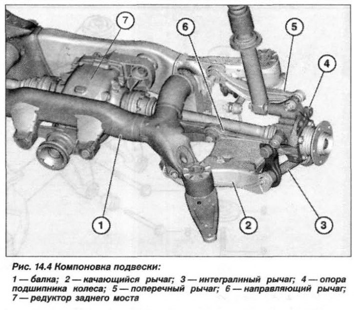
- swing arm to rear axle beam, front and rear;
- guide lever to the rear axle beam;
- transverse lever to the rear axle beam.
When replacing units and parts:
- rear axle beams;
- rocker arm;
- integral lever;
- wheel bearing supports (ball joint);
- transverse lever;
- guide lever.
The rear suspension layout is shown in Figure 14.4.
Body height dimension "A" (see fig. 13.45), the distance between the edge of the wheel rim and the lower edge of the wheel arch cover perpendicular to the center of the wheel. The value of "A" depends on the car model, the shock absorption system, and the size of the installed tires (Table 14.1). In this case, the difference in deviation from the specified value between all wheels should not exceed ±10.0 mm.
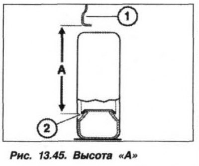
Table 14.1. Ground clearance height
| Suspension type | Car model | ||
| 3.0i/3.0d | 4.4І | 4.61s | |
| Steel spring | |||
| 17″ rim | 687 | — | — |
| 18″ rim | 700 | — | — |
| 19″ rim | 713 | — | — |
| 20″ rim | 726 | — | — |
| Single axle pneumatic, no low landing | |||
| 17″ rim | 695 | 687 | — |
| 18″ rim | 708 | 708 | 706 |
| 19″ rim | 721 | 721 | 718 |
| 20″ rim | 734 | 734 | 731 |
| Two-axle pneumatic, no low landing | |||
| 17″ rim | 687 | 687 | — |
| 18″ rim | 700 | 700 | — |
| 19″ rim | 713 | 713 | — |
| 20″ rim | 726 | 726 | — |
| Two-axle pneumatic, low-slung | |||
| 17″ rim | 672 | 672 | — |
| 18″ rim | 685 | 685 | — |
| 19″ rim | 698 | 698 | — |
| 20″ rim | 711 | 711 | — |