
Attention! Work on replacing the drive shaft (axle shaft) should only be carried out on a cold engine.
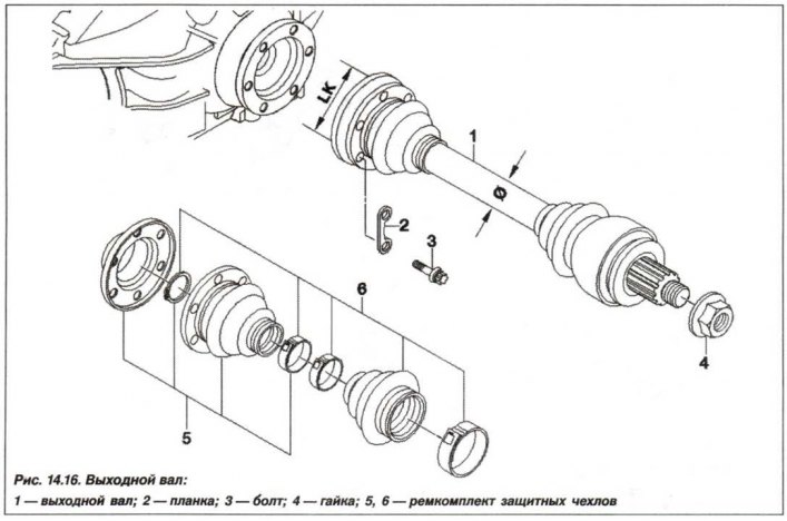
Replacement of the drive shaft (1, see Fig. 14.16) the rear wheel and its protective covers (5, 6) must be carried out in the following order.
Prepare the equipment "00.2.030", "21.2.120", "26.1.110" and "33.3.130".
On a vehicle with adjustable ride height, relieve pressure in the air supply system.
On a vehicle equipped with an M54 or M62 engine, unscrew the fastening of the intermediate and rear mufflers; on a vehicle equipped with an M57 or N62 engine, remove the exhaust system. Unscrew the bolts (3) and remove the locking plates (2).
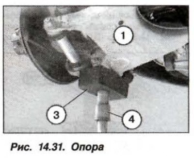
Install the device "00.2.030" (2, Fig. 14.31) with a wooden block (3) and raise the wheel bearing support (1) by 20 mm.
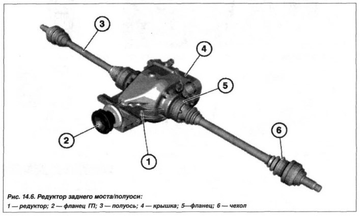
Remove the bolts (3, see Fig. 14.6) and remove them together with the plates (2).
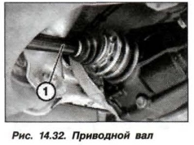
Press the axle shaft (1, Fig. 14.32).
Press the wheel drive shaft out of the wheel bearing support.
Remove the drive shaft (1) towards the central axis of the vehicle and clean it.
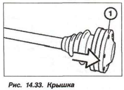
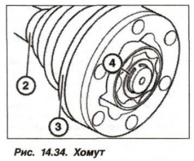
Place the drive shaft in a vice with soft jaws and remove the cover (1, Fig. 14.33) CV joint. Loosen the clamp (2, Fig. 14.34). Remove the bracket (3) from the protective cover and the retaining ring (4).
 |
 |
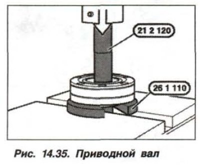
The size of the "26.1.110" tool depends on the diameter of the drive shaft. The inner ring of the bearing must rest on the collar of the tool. Press out the drive shaft (fig. 14.35) from the CV joint. For a hollow shaft, additionally use the "21.2.120" device. Do not disassemble the CV joint.
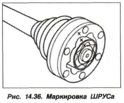
Note: If it is necessary to disassemble the CV joint, the location of the cage, separator and its housing should be marked with a punch (fig. 14.36).
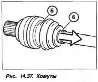
Check the CV joint for dirt and damage. Loosen the clamps (5 and 6, Fig. 14.37) and slide the boot (arrow) along the splined shaft. Thoroughly clean the assembled CV joint and completely remove the old grease. Put new grease into the CV joint from the repair kit (80 g).
Install a new protective cover on the rear axle side and remove the adhesive tape.
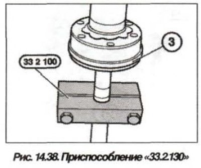
Lubricate the sealing surface of the cover with sealing gel and press it onto the CV joint using a thrust ring. Install the "33.2.100" device onto the shaft (fig. 14.38). Install a new retaining ring. Press the CV joint with cover (3) onto the splined shaft until a distinct click is heard.
Apply grease to the joint. Put the protective cover on the cover (3). Install new fastening clamps, with the clamp of the large clamp being located between the two holes for the CV joint fastening bolts.