
Raise the engine with the tool «11.0.000», about 10 mm. Set the steering gear to the middle position, the markings on the steering shaft and the steering gear must match. Remove the key from the ignition and lock the steering wheel.
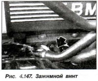
Loosen the lower clamping screw (pic. 4.147) dual cardan steering shaft. Disconnect the dual propshaft from the steering box.
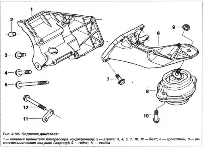
Loosen the nut (9, see fig. 4.146) on the engine mounting pad to the engine mount brackets on the left and right sides. Loosen the bolts (10) and disconnect the engine mounts from the front axle beam.
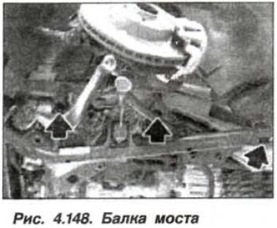
Support the front axle beam with a jack. Remove bolts (M12, arrows, fig. 4.148) connection of the front axle beam with the side member of the body. Lower the jack until the engine mounts can be removed.
The installation of the engine mounting pad should be carried out in the reverse order, while it is necessary to ensure that its centering pin enters the hole on the front axle beam.
Tighten new bolts securing the front axle beam to the body side member to a torque of 100 Nm (10.0 kgf·m). new nut (9, see fig. 4.146) pillow attachments (8) to bracket (6) engine tighten torque 56 Nm (5.6 kgf·m). New bolts (10, M8) fastening of a pillow to tighten the moment 42 Nm (4.2 kgf·m).
Clamp screw (M8) on a steel double universal joint, tighten to a torque of 24.0 Nm (2.4 kgf·m), or torque 28 Nm (2.8 kgf·m), if it is made of light alloy.