
Table of contents: Cleaning ↓ Checking the status ↓
- Home
- BMW 5 Series
- E28
- Power unit
- Engine overhaul
- Cleaning and checking the condition of the cylinder head and components
Cleaning and checking the condition of the cylinder head and components (BMW 5 Series E28)
A thorough cleaning of the cylinder head(s) and associated valve components followed by a detailed inspection of their condition will determine how much valve work will need to be done during an engine overhaul.
1. Use a scraper to remove all traces of old gasket and sealing compound from the sealing surfaces of the cylinder head, intake manifold, and exhaust manifold. Be especially careful not to damage the cylinder head. Special solvents for removing gaskets are available at auto parts stores.
2. Remove all deposits from the cooling channels.
3. Use a stiff brush to clean the various openings to remove any deposits that may have built up in them.
4. To remove any corrosion or thread sealant that may be present in the threaded holes, clean them with appropriately sized taps. If compressed air is available, use it to clear any debris from the holes after this operation.
5. Clean the cylinder head with solvent and dry thoroughly. Compressed air will speed up the drying process and ensure that the holes and recesses are clean.
6. Clean the rocker shafts/rocker arms/tappets, springs, valve springs, retainers and keepers with solvent, and then dry them thoroughly. To avoid mixing up the valve components, clean the valves one by one.
7. Use a scraper to remove any deposits from the valves, then use an electric brush to remove any carbon deposits from the valve heads and stems. Again, make sure that the valve components are not mixed up.
1. Carefully inspect the head for cracks, signs of coolant leakage, and other damage. If cracks are found, consult a mechanical workshop. If repair is not possible, a new cylinder head should be purchased.
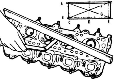
2. Using a flatness gauge and feeler gauges, check for any curvature of the head gasket sealing surface. If the curvature exceeds the limit specified in Table of sizes and adjustment data at the end of the Manual, it can be ground in a machine shop, provided that the thickness of the head is not less than the permissible one.
3. Inspect the valve seats of each combustion chamber. If they are significantly dented, cracked, or burned, the head will require service beyond the capabilities of a home repair shop.
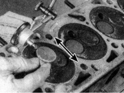
4. Check the clearance between the valve stem and the guide by measuring the lateral deflection of the stem with a dial indicator. The valve should be in the guide and about 2 mm above the seat. The total deflection of the valve stem measured with the indicator should be divided by two to obtain the actual clearance value. If there is any doubt about the condition of the valve guides after this, they should be checked by a machine shop (the price of this service is minimal).
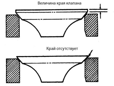
1. Carefully inspect the surface of each valve for uneven wear, distortion, cracks, dents, and burnt areas. Check the valve stem for galling and the stem neck for cracks. Rotate the valve and check for noticeable distortion. Check the stem end for dents and excessive wear. The presence of any of these defects indicates that the valves need to be serviced as described in Section Valve maintenance.
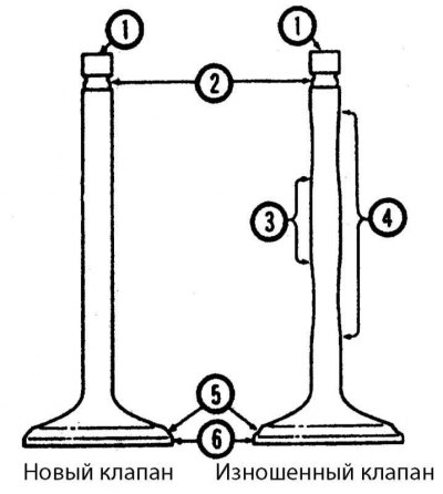
1 - End of valve
2 — Groove for crackers
3 - Rod (the most worn part)
4 - Rod (the most worn part)
5 - Valve chamfer
6 - Ascension
2. Measure the lift of each valve. A valve with a lift less than required must be replaced
1. Check the ends of all springs for wear. Before deciding to use springs in a rebuilt engine, it is necessary to check their rigidity using a special device (for this check, send the springs to a mechanical workshop).
2. Place each spring on a flat surface and check that they are plumb. If any of the springs are bent or warped, or possibly have a broken coil, replace the springs.
3. Check the spring retainers and crackers for obvious signs of wear and cracks. Any suspicious parts should be replaced, otherwise, if they fail while the engine is running, significant damage will occur.
1. Check the rocker arms for excessive wear on the ends that contact the valve stem and camshaft.
2. Check the radial clearance (see section Disassembling the cylinder head). If it is too large, then either the rocker arm bushing or the shaft (or both) is worn. To determine which component is more worn, move the rocker arm a certain distance along the shaft and measure the radial clearance again. If the clearance now meets specifications, then the shaft is probably the most worn component. If the clearance does not meet specifications, then the rocker arm bushings must be replaced.
Check the shafts for scoring, excessive wear, and other damage. The contact surfaces of the rocker arms with the shafts should be smooth. If there is a step at the contact boundary of the rocker arm with the shaft, the shaft is probably worn.
1. Check for wear, scoring, and dents on the tappets where they contact the ends of the valve stems and the pins. If there is significant wear on the tappets and camshaft, a new camshaft and tappets will need to be purchased.
2. Similarly, check the hydraulic tappets where they contact the wells in the cylinder head for wear, scoring, and dents. Sometimes the hydraulic tappets make noise when operating and need to be replaced, and this becomes noticeable when the engine is running. It is quite difficult to detect internal damage or wear on a hydraulic tappet when it is removed; if in doubt, a new set of hydraulic tappets must be installed.
1. Check the camshaft journals (circular sliding surfaces) and cams for scoring, nicks, chips and excessive wear. Measure the height of each intake and exhaust cam with a micrometer. Compare the heights of all intake and exhaust cams. If the measurements for all intake or exhaust cams differ by more than 0.08 mm, or if the camshaft shows any signs of wear, replace the camshaft.
2. Check the condition of the plain bearing surfaces in the cylinder head for scoring and other damage. If the bearing surfaces are scored or damaged, the cylinder head is usually replaced, since the bearings are machined surfaces in the cylinder head.
3. Measure the camshaft journals with a micrometer and record the measurement results.
4. Using a telescopic gauge or a micrometer - bore gauge, measure the diameters of the camshaft bearings in the cylinder head (on the M40 engine, pre-install the bearing caps). To obtain the lubrication clearance, subtract the inside diameter of the corresponding bearing from the journal size of the camshaft. Compare the lubrication clearance with the value given in Table of sizes and adjustment data at the end of the manual. If it does not match, a new cylinder head and/or a new camshaft will be required.
If the engine has experienced severe overheating, the cylinder head is likely warped (see p. 4).
Cleaning
1. Use a scraper to remove all traces of old gasket and sealing compound from the sealing surfaces of the cylinder head, intake manifold, and exhaust manifold. Be especially careful not to damage the cylinder head. Special solvents for removing gaskets are available at auto parts stores.
2. Remove all deposits from the cooling channels.
3. Use a stiff brush to clean the various openings to remove any deposits that may have built up in them.
4. To remove any corrosion or thread sealant that may be present in the threaded holes, clean them with appropriately sized taps. If compressed air is available, use it to clear any debris from the holes after this operation.
When using compressed air, wear safety glasses.
5. Clean the cylinder head with solvent and dry thoroughly. Compressed air will speed up the drying process and ensure that the holes and recesses are clean.
There are chemical carbon removers available and they can be very helpful in cleaning cylinder heads and valve train components. However, these products are very aggressive and should be used with caution. Follow the instructions on the packaging.
6. Clean the rocker shafts/rocker arms/tappets, springs, valve springs, retainers and keepers with solvent, and then dry them thoroughly. To avoid mixing up the valve components, clean the valves one by one.
Do not clean the hydraulic lifters of the M40 engine; leave them completely immersed in oil.
7. Use a scraper to remove any deposits from the valves, then use an electric brush to remove any carbon deposits from the valve heads and stems. Again, make sure that the valve components are not mixed up.
Checking the status
Before deciding whether to take the machine to a machine shop, make sure that all of the following condition checks have been completed. Make a checklist.
Cylinder head
1. Carefully inspect the head for cracks, signs of coolant leakage, and other damage. If cracks are found, consult a mechanical workshop. If repair is not possible, a new cylinder head should be purchased.
2. Using a flatness gauge and feeler gauges, check for any curvature of the head gasket sealing surface. If the curvature exceeds the limit specified in Table of sizes and adjustment data at the end of the Manual, it can be ground in a machine shop, provided that the thickness of the head is not less than the permissible one.
3. Inspect the valve seats of each combustion chamber. If they are significantly dented, cracked, or burned, the head will require service beyond the capabilities of a home repair shop.
4. Check the clearance between the valve stem and the guide by measuring the lateral deflection of the stem with a dial indicator. The valve should be in the guide and about 2 mm above the seat. The total deflection of the valve stem measured with the indicator should be divided by two to obtain the actual clearance value. If there is any doubt about the condition of the valve guides after this, they should be checked by a machine shop (the price of this service is minimal).
Valves
1. Carefully inspect the surface of each valve for uneven wear, distortion, cracks, dents, and burnt areas. Check the valve stem for galling and the stem neck for cracks. Rotate the valve and check for noticeable distortion. Check the stem end for dents and excessive wear. The presence of any of these defects indicates that the valves need to be serviced as described in Section Valve maintenance.
1 - End of valve
2 — Groove for crackers
3 - Rod (the most worn part)
4 - Rod (the most worn part)
5 - Valve chamfer
6 - Ascension
2. Measure the lift of each valve. A valve with a lift less than required must be replaced
Valve components
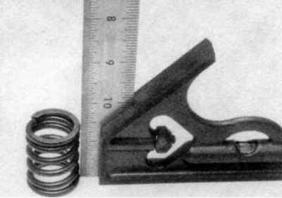
1. Check the ends of all springs for wear. Before deciding to use springs in a rebuilt engine, it is necessary to check their rigidity using a special device (for this check, send the springs to a mechanical workshop).
2. Place each spring on a flat surface and check that they are plumb. If any of the springs are bent or warped, or possibly have a broken coil, replace the springs.
3. Check the spring retainers and crackers for obvious signs of wear and cracks. Any suspicious parts should be replaced, otherwise, if they fail while the engine is running, significant damage will occur.
Rocker arms (engines M10, M20 and M30)
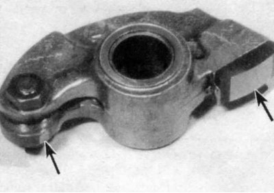
The exhaust rocker arms are most susceptible to wear and should be inspected with particular care.
1. Check the rocker arms for excessive wear on the ends that contact the valve stem and camshaft.
2. Check the radial clearance (see section Disassembling the cylinder head). If it is too large, then either the rocker arm bushing or the shaft (or both) is worn. To determine which component is more worn, move the rocker arm a certain distance along the shaft and measure the radial clearance again. If the clearance now meets specifications, then the shaft is probably the most worn component. If the clearance does not meet specifications, then the rocker arm bushings must be replaced.
Rocker shafts (engines M10, M20 and M30)
Check the shafts for scoring, excessive wear, and other damage. The contact surfaces of the rocker arms with the shafts should be smooth. If there is a step at the contact boundary of the rocker arm with the shaft, the shaft is probably worn.
Hydraulic tappets (m40 engine)
1. Check for wear, scoring, and dents on the tappets where they contact the ends of the valve stems and the pins. If there is significant wear on the tappets and camshaft, a new camshaft and tappets will need to be purchased.
2. Similarly, check the hydraulic tappets where they contact the wells in the cylinder head for wear, scoring, and dents. Sometimes the hydraulic tappets make noise when operating and need to be replaced, and this becomes noticeable when the engine is running. It is quite difficult to detect internal damage or wear on a hydraulic tappet when it is removed; if in doubt, a new set of hydraulic tappets must be installed.
Camshaft
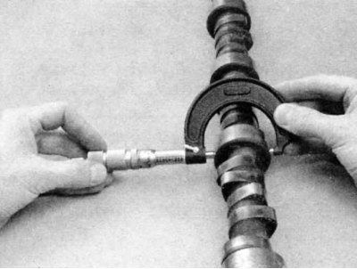
1. Check the camshaft journals (circular sliding surfaces) and cams for scoring, nicks, chips and excessive wear. Measure the height of each intake and exhaust cam with a micrometer. Compare the heights of all intake and exhaust cams. If the measurements for all intake or exhaust cams differ by more than 0.08 mm, or if the camshaft shows any signs of wear, replace the camshaft.
2. Check the condition of the plain bearing surfaces in the cylinder head for scoring and other damage. If the bearing surfaces are scored or damaged, the cylinder head is usually replaced, since the bearings are machined surfaces in the cylinder head.
Mechanical workshop (in particular, specializing in BMW) or the dealer branch may offer an alternative to replacing the cylinder head if the only problem is minor scratches on the camshaft bearing surfaces.
3. Measure the camshaft journals with a micrometer and record the measurement results.
4. Using a telescopic gauge or a micrometer - bore gauge, measure the diameters of the camshaft bearings in the cylinder head (on the M40 engine, pre-install the bearing caps). To obtain the lubrication clearance, subtract the inside diameter of the corresponding bearing from the journal size of the camshaft. Compare the lubrication clearance with the value given in Table of sizes and adjustment data at the end of the manual. If it does not match, a new cylinder head and/or a new camshaft will be required.
Before installing a new cylinder head, have the old one checked by a mechanic (especially in the BMW specialty). Maybe they can restore it.
This article is available at russian, bulgarian, belarusian, ukrainian, serbian, croatian, romanian, polish, slovak, hungarian
Article verified: Zhuravleva Isolda
Share information:
Previous articles
БМВ E28: Engine overhaul
Next articles
Similar articles on other types of BMW cars:
Cylinder head and valve mechanism — cleaning and checking the… BMW 3 Series E46 (1998-2006, petrol)
Checking the condition of suspension and steering components BMW 3 Series E46 (1998-2006)
Cylinder head — cleaning and inspection BMW 7 Series E32 (1986-1994)
Checking the condition of suspension and steering components BMW 7 Series E38 (1994-2001)
Cylinder head BMW X3 E83 (2003-2010)
Checking the sealing plane of the cylinder head BMW X5 E53 (1999-2006)
Link in different formats to this page
Visitor comments
No comments yet
- General information
- Governing bodies
- Manual
- Maintenance
- Power unit
- Engine repair
- Lubrication system
- Cooling system
- Ignition system
- Supply system
- Injection system (gasoline)
- Injection system (diesel)
- Exhaust system
- Transmission
- Clutch
- Car gearbox
- Front axle
- Rear axle
- Chassis
- Steering
- Brake system
- Wheels and tires
- Body
- Interior
- Exterior
- Heating system
- Electrical equipment
- Equipment and devices
- Power devices
- Windscreen wipers
- Electrical circuits
- General information
- Manual
- Maintenance
- Power unit
- Engine repair
- Ignition system
- Engine lubrication system
- Cooling system
- Fuel system (gasoline)
- Fuel system (diesel)
- Exhaust system
- Transmission
- Clutch
- Car gearbox
- Chassis
- Front and rear suspension
- Steering
- Brake system
- Body
- Exterior
- Interior
- Electrical equipment
- Heating system
- Equipment and devices
- Power devices
- Electrical circuits
- General information
- Manual
- Maintenance
- Power unit
- Engine in a car
- Engine overhaul
- Cooling system
- Supply system
- Ignition system
- Control system
- Transmission
- Clutch
- Manual gearbox
- Automatic gearbox
- Transmission line
- Chassis
- Steering
- Front suspension
- Rear suspension
- Brake system
- Body
- Body elements
- Car care and painting
- Electrical equipment
- Heater and air conditioner
- Equipment and devices
- Starter and generator
- Electrical circuits
- General information
- Operation and maintenance
- Specifications
- Power unit
- Engine repair
- Cooling and lubrication system
- Supply system
- Ecotronic power supply system
- Fuel injection system
- Ignition system
- Transmission
- Clutch
- Gearbox BMW 242/4
- Gearbox Getrag 262/8
- Gearbox Getrag 265/6
- Automatic gearbox
- Cardan gear
- Rear axle
- Chassis
- Steering
- Front suspension
- Rear suspension
- Brake system
- Electrical equipment
- Equipment and devices
- Electrical circuits