
- Home
- BMW 5 Series
- E28
- Power unit
- Engine overhaul
- Cylinder head assembly
Cylinder head assembly (BMW 5 Series E28)
1. Before assembly, make sure the cylinder head is perfectly clean.
2. If the valve head was sent to the workshop for valve service, the valves will already be installed. Begin the assembly procedure from step 1.
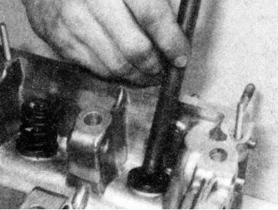
3. Starting at either end of the head, install the first valve, lubricating its stem with molybdenum disulfide grease or engine oil.
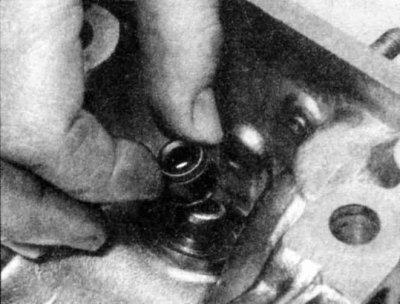
4. Lubricate the flange of the oil deflector cap, carefully put it on the end of the valve,..
...then slide it down the stem toward the guide. Using a hammer and long socket or valve stem seal installer, carefully tap the seal until it is seated completely on the guide. Do not bend or twist the seal during installation or it will not seat properly against the valve stem.
5. Install the spring seat or washer(s) onto the guide, then the spring and spring retainer.
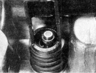
6. Compress the spring with the compressor and carefully install the crackers into the groove, then carefully release the compressor and make sure that the crackers are installed correctly.
7. Repeat steps 3 - 6 for each valve. Make sure the components are installed in their correct places - do not mix them up!
1. Install the rocker arms and shafts in the reverse order of disassembly. Make sure the shafts are installed in the correct position. The flat guide cutouts and small oil holes should be facing inward; large lubrication holes - down, towards the valve guides.
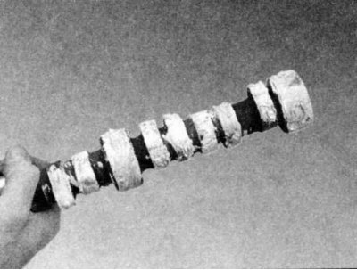
2. Lubricate the camshaft journals and lobes with engine assembly paste or molybdenum disulphide grease, then carefully insert it into the cylinder head, turning it so that the lobes bypass the rocker arms. In addition, it will be necessary to compress the valve springs through the rocker arms as described in Section Disassembling the cylinder head, so that the cams pass under the rocker arms. Be very careful not to scratch or dent the camshaft bearing surfaces in the cylinder head.
1. Lubricate the hydraulic lifter wells in the cylinder head, then install them in their places.
2. Install the thrust discs on the valves and the tappets on the valves and hydraulic tappet rods, maintaining their previous location.
3. Lubricate the camshaft bearing surfaces in the cylinder head.
4. Install the camshaft into the cylinder head so that both valves of cylinder No.1 are open and the valves of cylinder No.4 are in the switching state (the outlet closes, the inlet opens). Cylinder No.1 is located on the timing belt side.
5. Lubricate the bearing cap surfaces, then install them in the correct position and insert the mounting bolts. Tighten the bolts to the required torque in stages, one by one.
6. Install a new oil seal into the front camshaft bearing cap (see Part Repair work carried out without removing the engine from the vehicle).
1. Install the oil supply pipe with new seals to the top of the cylinder head, then tighten the bolts to the required torque.
2. The cylinder head is ready for installation (see Part Repair work carried out without removing the engine from the vehicle).
2. If the valve head was sent to the workshop for valve service, the valves will already be installed. Begin the assembly procedure from step 1.
3. Starting at either end of the head, install the first valve, lubricating its stem with molybdenum disulfide grease or engine oil.
4. Lubricate the flange of the oil deflector cap, carefully put it on the end of the valve,..
...then slide it down the stem toward the guide. Using a hammer and long socket or valve stem seal installer, carefully tap the seal until it is seated completely on the guide. Do not bend or twist the seal during installation or it will not seat properly against the valve stem.
On some engines the intake and exhaust valve stem seals are different - do not confuse them.
5. Install the spring seat or washer(s) onto the guide, then the spring and spring retainer.
6. Compress the spring with the compressor and carefully install the crackers into the groove, then carefully release the compressor and make sure that the crackers are installed correctly.
If necessary, apply a small amount of grease to each cracker to help keep them in place.
7. Repeat steps 3 - 6 for each valve. Make sure the components are installed in their correct places - do not mix them up!
Engines M10, M20 and M30
1. Install the rocker arms and shafts in the reverse order of disassembly. Make sure the shafts are installed in the correct position. The flat guide cutouts and small oil holes should be facing inward; large lubrication holes - down, towards the valve guides.
2. Lubricate the camshaft journals and lobes with engine assembly paste or molybdenum disulphide grease, then carefully insert it into the cylinder head, turning it so that the lobes bypass the rocker arms. In addition, it will be necessary to compress the valve springs through the rocker arms as described in Section Disassembling the cylinder head, so that the cams pass under the rocker arms. Be very careful not to scratch or dent the camshaft bearing surfaces in the cylinder head.
M40 engines
1. Lubricate the hydraulic lifter wells in the cylinder head, then install them in their places.
2. Install the thrust discs on the valves and the tappets on the valves and hydraulic tappet rods, maintaining their previous location.
3. Lubricate the camshaft bearing surfaces in the cylinder head.
4. Install the camshaft into the cylinder head so that both valves of cylinder No.1 are open and the valves of cylinder No.4 are in the switching state (the outlet closes, the inlet opens). Cylinder No.1 is located on the timing belt side.
5. Lubricate the bearing cap surfaces, then install them in the correct position and insert the mounting bolts. Tighten the bolts to the required torque in stages, one by one.
6. Install a new oil seal into the front camshaft bearing cap (see Part Repair work carried out without removing the engine from the vehicle).
All engines
1. Install the oil supply pipe with new seals to the top of the cylinder head, then tighten the bolts to the required torque.
2. The cylinder head is ready for installation (see Part Repair work carried out without removing the engine from the vehicle).
This article is available at russian, bulgarian, belarusian, ukrainian, serbian, croatian, romanian, polish, slovak, hungarian
Article verified: Zhuravleva Isolda
Share information:
Previous articles
БМВ E28: Engine overhaul
Next articles
Similar articles on other types of BMW cars:
Cylinder head assembly BMW 3 Series E21 (1975-1983)
Cylinder head — assembly BMW 3 Series E46 (1998-2006, petrol)
Cylinder head — assembly BMW 7 Series E32 (1986-1994)
Removal and installation cylinder head covers BMW 7 Series E38 (1994-2001)
Cylinder head BMW X3 E83 (2003-2010)
Cylinder head — design description BMW X5 E53 (1999-2006)
Link in different formats to this page
Visitor comments
No comments yet
- General information
- Governing bodies
- Manual
- Maintenance
- Power unit
- Engine repair
- Lubrication system
- Cooling system
- Ignition system
- Supply system
- Injection system (gasoline)
- Injection system (diesel)
- Exhaust system
- Transmission
- Clutch
- Car gearbox
- Front axle
- Rear axle
- Chassis
- Steering
- Brake system
- Wheels and tires
- Body
- Interior
- Exterior
- Heating system
- Electrical equipment
- Equipment and devices
- Power devices
- Windscreen wipers
- Electrical circuits
- General information
- Manual
- Maintenance
- Power unit
- Engine repair
- Ignition system
- Engine lubrication system
- Cooling system
- Fuel system (gasoline)
- Fuel system (diesel)
- Exhaust system
- Transmission
- Clutch
- Car gearbox
- Chassis
- Front and rear suspension
- Steering
- Brake system
- Body
- Exterior
- Interior
- Electrical equipment
- Heating system
- Equipment and devices
- Power devices
- Electrical circuits
- General information
- Manual
- Maintenance
- Power unit
- Engine in a car
- Engine overhaul
- Cooling system
- Supply system
- Ignition system
- Control system
- Transmission
- Clutch
- Manual gearbox
- Automatic gearbox
- Transmission line
- Chassis
- Steering
- Front suspension
- Rear suspension
- Brake system
- Body
- Body elements
- Car care and painting
- Electrical equipment
- Heater and air conditioner
- Equipment and devices
- Starter and generator
- Electrical circuits
- General information
- Operation and maintenance
- Specifications
- Power unit
- Engine repair
- Cooling and lubrication system
- Supply system
- Ecotronic power supply system
- Fuel injection system
- Ignition system
- Transmission
- Clutch
- Gearbox BMW 242/4
- Gearbox Getrag 262/8
- Gearbox Getrag 265/6
- Automatic gearbox
- Cardan gear
- Rear axle
- Chassis
- Steering
- Front suspension
- Rear suspension
- Brake system
- Electrical equipment
- Equipment and devices
- Electrical circuits