
- Home
- BMW 5 Series
- E28
- Power unit
- Engine overhaul
- Disassembling the cylinder head
Disassembling the cylinder head (BMW 5 Series E28)
1. Remove the cylinder head (see Part Repair work carried out without removing the engine from the vehicle).
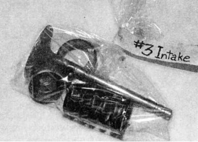
2. Remove the oil pipe from the top of the cylinder head. Make sure you note the position of all gaskets and washers for assembly.
1. Adjust all valves to maximum clearance by rotating the eccentric on the valve side of the rocker arm towards the center of the head (if necessary, refer to Chapter Routine car maintenance).
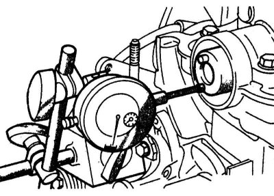
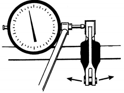
2. Before removing the thrust plate, measure the axial play of the camshaft by installing a dial indicator on the front side of the cylinder head and placing the feeler gauge on the camshaft. Move the camshaft back and forth in the cylinder head. The indicator reading will be the axial play.
3. Compare the readings with the values given in Table of sizes and adjustment data at the end of the Guide.
4. Loosen the bolts and remove the camshaft thrust plate.
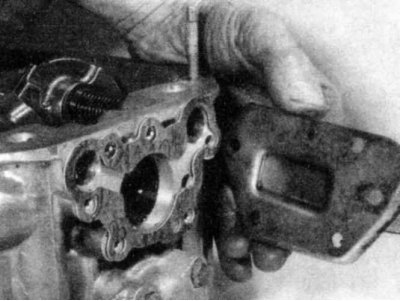
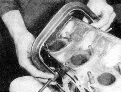
5. Remove the cover from the rear surface of the cylinder head - when removing the cover, remember the location of all gaskets, washers and seals.
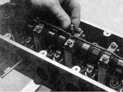
6. Remove the retaining clips from the rocker arms.
7. Before removing the rocker arm shafts, measure the rocker arm radial clearances using a dial indicator and compare the results with the values given in Table of sizes and adjustment data at the end of the manual. Rotate the rocker arm on the shaft in both directions without sliding it along the shaft. The full swing at the end of the rocker arm facing the camshaft will be the radial clearance. If the clearance is too large, the rocker arm bushing or the rocker arm shaft, or both, will need to be replaced.
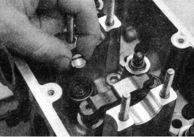
8. Remove the rubber or threaded stop plugs from the front of the cylinder head, depending on the application. There is a plug at the front of each rocker shaft.
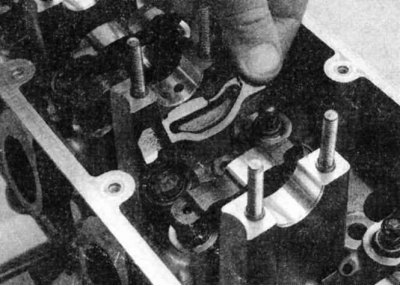
9. Rotate the camshaft to a position where as many rocker arms as possible are free (will not compress the corresponding valve springs).
10. For the remaining rocker arms that remain compressing the valve springs, BMW suggests using a special fork-shaped tool to press the rocker arms onto the springs (thereby removing the spring force from the camshaft cam). If this tool is not available, insert standard screwdrivers into the gaps above the eccentric adjusters on the valve side of the rocker arms. Use the screwdrivers to push the rocker arms onto the valve springs and hold them in this position while removing the camshaft (see next paragraph). This operation will require at least one assistant, as there are usually three or four valve springs to compress. If no assistant is available, you can try to secure the screwdrivers that compress the valve springs to a board with strong wire.
11. When all rocker arms are out of contact with the camshaft lobes, slowly and carefully remove the camshaft from the front of the cylinder head.
12. It may be necessary to rotate the camshaft when removing it.
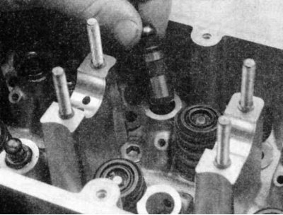
13. Once the camshaft has been removed, carefully remove the rocker shafts. On models without threaded holes in the front of the shafts, remove the shafts through the back of the cylinder head using a hammer and a strong wooden rod that has a diameter slightly smaller than the rocker shaft.
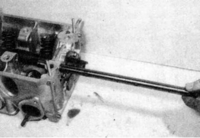
14. For rocker arm shafts with threaded holes on the front side, use a sliding hammer to remove the shaft.
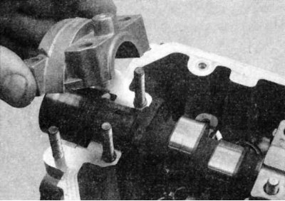
15. After removing all the rocker shafts from the cylinder head, remove the rocker arms themselves one by one.
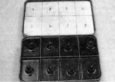
16. Place each rocker arm in a labeled bag so that they will be installed in their original positions during reassembly. When removing the rocker shafts, note their positions. The guide flats and small oil holes point inward; the large oil drain holes face down towards the valve guides. Also mark the rocker shafts so that they can be installed into the cylinder head in the same position.
1. Check that the camshaft bearing caps are numbered or their position is marked.
2. Therefore, unscrew and remove the camshaft bearing cap mounting bolts,..
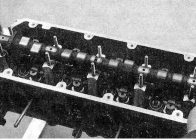
...then remove the camshaft covers of the M40 engine
3. Lift the camshaft from the top of the cylinder head and remove the oil seal from the end facing the timing gear.
4. Prepare a box with compartments filled with engine oil to hold the hydraulic tappets so that they are stored in their proper locations. Also prepare another box for the tappets.
5. Remove the pushers...
...and thrust discs,..
...then remove the hydraulic tappets from the wells in the cylinder head.
1. Before removing valves, label and store them and associated components so that they can be stored separately and reinstalled in the same guides.
2. Compress the first valve spring compressor and remove the crackers. Carefully release the valve spring compressor and remove the retainer, spring and spring seat (if applied).
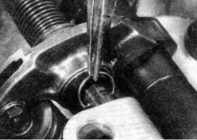
3. Remove the valve stem seal from the valve head and then remove it from the guide.
4. Repeat the operation for the remaining valves. Remember to keep all the parts of one valve together so that they can be reinstalled in their original places.
5. Once the valves and related components have been removed and stored in the proper order, the cylinder head should be thoroughly cleaned and inspected. If a complete overhaul is being performed, complete engine disassembly before cleaning and inspecting the head.
6. If the valve gets stuck in the guide (not extracted), insert it back into the head and use a fine file or abrasive stone to remove any burrs in the area of the groove under the crackers.
2. Remove the oil pipe from the top of the cylinder head. Make sure you note the position of all gaskets and washers for assembly.
It is important to replace the seals under the tube mounting bolts.
Engines M10, M20 and M30
1. Adjust all valves to maximum clearance by rotating the eccentric on the valve side of the rocker arm towards the center of the head (if necessary, refer to Chapter Routine car maintenance).
2. Before removing the thrust plate, measure the axial play of the camshaft by installing a dial indicator on the front side of the cylinder head and placing the feeler gauge on the camshaft. Move the camshaft back and forth in the cylinder head. The indicator reading will be the axial play.
3. Compare the readings with the values given in Table of sizes and adjustment data at the end of the Guide.
4. Loosen the bolts and remove the camshaft thrust plate.
There are two different positions of the thrust plate. On M10 and M30 engines, it is fixed in the front part of the cylinder head behind the flange of the timing gear. On M20 and M40 engines, the thrust plate is located inside the head near the rocker shafts in the front part of the cylinder head.
5. Remove the cover from the rear surface of the cylinder head - when removing the cover, remember the location of all gaskets, washers and seals.
6. Remove the retaining clips from the rocker arms.
There are several types of clamps. Wire clamps are installed on both sides of the rocker arm; the spring clamp is installed on the rocker arm itself and covers it on one side.
7. Before removing the rocker arm shafts, measure the rocker arm radial clearances using a dial indicator and compare the results with the values given in Table of sizes and adjustment data at the end of the manual. Rotate the rocker arm on the shaft in both directions without sliding it along the shaft. The full swing at the end of the rocker arm facing the camshaft will be the radial clearance. If the clearance is too large, the rocker arm bushing or the rocker arm shaft, or both, will need to be replaced.
8. Remove the rubber or threaded stop plugs from the front of the cylinder head, depending on the application. There is a plug at the front of each rocker shaft.
If the engine has welded plugs at the front of the rocker shafts, take the cylinder head to a machine shop to remove them to avoid damaging the cylinder head or rocker shafts.
9. Rotate the camshaft to a position where as many rocker arms as possible are free (will not compress the corresponding valve springs).
10. For the remaining rocker arms that remain compressing the valve springs, BMW suggests using a special fork-shaped tool to press the rocker arms onto the springs (thereby removing the spring force from the camshaft cam). If this tool is not available, insert standard screwdrivers into the gaps above the eccentric adjusters on the valve side of the rocker arms. Use the screwdrivers to push the rocker arms onto the valve springs and hold them in this position while removing the camshaft (see next paragraph). This operation will require at least one assistant, as there are usually three or four valve springs to compress. If no assistant is available, you can try to secure the screwdrivers that compress the valve springs to a board with strong wire.
Make sure the wire is securely fastened to the board and to the screwdrivers, otherwise the screwdrivers may pop out of the cylinder head and cause injury.
11. When all rocker arms are out of contact with the camshaft lobes, slowly and carefully remove the camshaft from the front of the cylinder head.
12. It may be necessary to rotate the camshaft when removing it.
Be very careful not to scratch the camshaft bearing journals when removing them.
13. Once the camshaft has been removed, carefully remove the rocker shafts. On models without threaded holes in the front of the shafts, remove the shafts through the back of the cylinder head using a hammer and a strong wooden rod that has a diameter slightly smaller than the rocker shaft.
14. For rocker arm shafts with threaded holes on the front side, use a sliding hammer to remove the shaft.
15. After removing all the rocker shafts from the cylinder head, remove the rocker arms themselves one by one.
16. Place each rocker arm in a labeled bag so that they will be installed in their original positions during reassembly. When removing the rocker shafts, note their positions. The guide flats and small oil holes point inward; the large oil drain holes face down towards the valve guides. Also mark the rocker shafts so that they can be installed into the cylinder head in the same position.
M40 engines
Keep the cylinder head in a vertical position until all hydraulic lifters are removed. Failure to do so may cause the hydraulic lifters to leak oil and become inoperative.
1. Check that the camshaft bearing caps are numbered or their position is marked.
2. Therefore, unscrew and remove the camshaft bearing cap mounting bolts,..
...then remove the camshaft covers of the M40 engine
3. Lift the camshaft from the top of the cylinder head and remove the oil seal from the end facing the timing gear.
4. Prepare a box with compartments filled with engine oil to hold the hydraulic tappets so that they are stored in their proper locations. Also prepare another box for the tappets.
5. Remove the pushers...
...and thrust discs,..
...then remove the hydraulic tappets from the wells in the cylinder head.
All engines
1. Before removing valves, label and store them and associated components so that they can be stored separately and reinstalled in the same guides.
2. Compress the first valve spring compressor and remove the crackers. Carefully release the valve spring compressor and remove the retainer, spring and spring seat (if applied).
3. Remove the valve stem seal from the valve head and then remove it from the guide.
4. Repeat the operation for the remaining valves. Remember to keep all the parts of one valve together so that they can be reinstalled in their original places.
5. Once the valves and related components have been removed and stored in the proper order, the cylinder head should be thoroughly cleaned and inspected. If a complete overhaul is being performed, complete engine disassembly before cleaning and inspecting the head.
6. If the valve gets stuck in the guide (not extracted), insert it back into the head and use a fine file or abrasive stone to remove any burrs in the area of the groove under the crackers.
This article is available at russian, bulgarian, belarusian, ukrainian, serbian, croatian, romanian, polish, slovak, hungarian
Article verified: Zhuravleva Isolda
Share information:
Previous articles
БМВ E28: Engine overhaul
Next articles
Similar articles on other types of BMW cars:
Disassembling the cylinder head BMW 3 Series E21 (1975-1983)
Removal and installation the cylinder head BMW 3 Series E30 (1982-1994)
Cylinder Head Cover — Removal and Installation BMW 7 Series E32 (1986-1994)
Removal and installation cylinder head covers BMW 7 Series E38 (1994-2001)
Cylinder head BMW X3 E83 (2003-2010)
Cylinder head — design description BMW X5 E53 (1999-2006)
Link in different formats to this page
Visitor comments
No comments yet
- General information
- Governing bodies
- Manual
- Maintenance
- Power unit
- Engine repair
- Lubrication system
- Cooling system
- Ignition system
- Supply system
- Injection system (gasoline)
- Injection system (diesel)
- Exhaust system
- Transmission
- Clutch
- Car gearbox
- Front axle
- Rear axle
- Chassis
- Steering
- Brake system
- Wheels and tires
- Body
- Interior
- Exterior
- Heating system
- Electrical equipment
- Equipment and devices
- Power devices
- Windscreen wipers
- Electrical circuits
- General information
- Manual
- Maintenance
- Power unit
- Engine repair
- Ignition system
- Engine lubrication system
- Cooling system
- Fuel system (gasoline)
- Fuel system (diesel)
- Exhaust system
- Transmission
- Clutch
- Car gearbox
- Chassis
- Front and rear suspension
- Steering
- Brake system
- Body
- Exterior
- Interior
- Electrical equipment
- Heating system
- Equipment and devices
- Power devices
- Electrical circuits
- General information
- Manual
- Maintenance
- Power unit
- Engine in a car
- Engine overhaul
- Cooling system
- Supply system
- Ignition system
- Control system
- Transmission
- Clutch
- Manual gearbox
- Automatic gearbox
- Transmission line
- Chassis
- Steering
- Front suspension
- Rear suspension
- Brake system
- Body
- Body elements
- Car care and painting
- Electrical equipment
- Heater and air conditioner
- Equipment and devices
- Starter and generator
- Electrical circuits
- General information
- Operation and maintenance
- Specifications
- Power unit
- Engine repair
- Cooling and lubrication system
- Supply system
- Ecotronic power supply system
- Fuel injection system
- Ignition system
- Transmission
- Clutch
- Gearbox BMW 242/4
- Gearbox Getrag 262/8
- Gearbox Getrag 265/6
- Automatic gearbox
- Cardan gear
- Rear axle
- Chassis
- Steering
- Front suspension
- Rear suspension
- Brake system
- Electrical equipment
- Equipment and devices
- Electrical circuits