
Table of contents: Checking the lubrication clearances…↓ Final installation of connecting rods ↓
- Home
- BMW 5 Series
- E28
- Power unit
- Engine overhaul
- Installing pistons/connecting rods assemblies and checking lubrication clearances in connecting rod bearings
Installing pistons/connecting rods assemblies and checking lubrication clearances in connecting rod bearings (BMW 5 Series E28)
1. Before installing the piston/connecting rod assemblies, the cylinder walls must be spotlessly clean, the top edge of each cylinder must be chamfered and the crankshaft must be installed.
2. Remove the cover from connecting rod #1 (refer to the marks made during removal). Remove the old bearing shells and wipe the connecting rod and cap bearing surfaces with a clean, lint-free cloth. They should be spotlessly clean.
1. Clean the back of the new upper bearing shell, then install it on the connecting rod. Make sure the lip of the bearing shell aligns with the recess in the connecting rod. Do not hammer the bearing shell into place, and be very careful not to scratch or nick the surface. Again, make sure the lip of the shell aligns with the recess in the cap, and do not apply any grease. It is essential that the mating surfaces of the bearing and connecting rod are spotlessly clean and free of oil during this check.
2. Set the piston ring gaps at 120° angles to each other.
3. Place a piece of plastic or rubber tubing over each connecting rod cap bolt.
4. Lubricate the piston and rings with clean engine oil and install the piston compressor on the piston. Leave the piston skirt protruding 6 or 7 mm to insert the piston into the cylinder. The rings should be compressed until they are flush with the piston.
5. Turn the crankshaft so that the journal of the bearing of connecting rod No.1 is at BDC (bottom dead center). Apply a layer of engine oil to the cylinder walls.
6. Carefully insert the piston/connecting rod assembly into cylinder #1, aligning the mark or notch on the piston crown toward the front of the engine, and rest the bottom edge of the compressor against the cylinder block.
7. Tap the top edge of the ring squeezer to ensure it makes contact with the block all the way around.
8. Lightly tap the piston bottom with a wooden hammer handle, while directing the end of the connecting rod toward the crankshaft journal. Working slowly, if you feel resistance as the piston moves through the cylinder, stop pressing immediately. Find what is interfering and eliminate the cause. Do not use force under any circumstances - you can break the ring and/or piston.
9. When the piston/connecting rod assemblies are installed, the bearing lubrication clearance should be checked before final tightening of the connecting rod cap bolts.
10. Cut a piece of plastic wire of the appropriate size, slightly smaller than the width of the connecting rod bearing, and place it on the journal of connecting rod No.1, parallel to the axis of the crankshaft.
11. Clean the bearing surface of the connecting rod cap, remove the protective tubes from the connecting rod bolts and install the connecting rod cap. Make sure that the mark on the cap matches the mark on the connecting rod.
12. Install the nuts and bolts and tighten to the torque specified in Table of sizes and adjustment data at the end of the manual. On M10 and M30 engines, achieve final thrust in three stages.
13. Loosen the nut and remove the connecting rod cover, being careful not to displace the plastic wire.
14. Compare the width of the flattened wire with the scale printed on the wire package. Compare the value with the requirements Size charts and adjustment data at the end of the manual to ensure the gap is correct.
15. If the clearance differs from the required one, the bearing shells may be of the wrong size (what does it mean to buy new liners). Before deciding whether to purchase different bearings, make sure there is no dirt or oil present when measuring the clearance between the bearings and the rods or caps. Also, re-measure the journal diameter. If the wire width was not uniform, the journal may be tapered (see section Checking the condition of the crankshaft).
1. Carefully remove all traces of wire material from the journal and/or bearing surface. Be careful not to scratch the bearing surface - use your fingernail or the edge of a credit card to do this.
2. Ensure that the bearing surfaces are spotlessly clean, then apply an even coat of molybdenum disulphide grease or engine oil to both surfaces. You will need to push the piston into the cylinder to access the connecting rod bearing shell surface - first ensure that the connecting rod bolts, if used, have protective tubes fitted.
3. Slide the connecting rod back into place on the journal and remove the protective tubes from the connecting rod cap bolts. Install the connecting rod caps and tighten the nuts/bolts to the required torque.
4. Repeat the same procedure for the remaining pistons/connecting rods.
5. The following are important circumstances:
6. After all pistons/connecting rods are correctly installed, turn the crankshaft by hand several times to check for obvious binding.
7. Check the lateral play of the connecting rods (see section Removal the crankshaft).
8. Compare the measured lateral clearance with the requirements Size charts and adjustment data at the end of the manual to ensure that it is correct. If the backlash was correct before disassembly and the original crankshaft and connecting rods were installed, it should be retained. If a new crankshaft or new connecting rods were installed, the backlash may not be correct. If so, the connecting rods should be removed and sent to a machine shop for inspection.
2. Remove the cover from connecting rod #1 (refer to the marks made during removal). Remove the old bearing shells and wipe the connecting rod and cap bearing surfaces with a clean, lint-free cloth. They should be spotlessly clean.
Checking the lubrication clearances of connecting rod bearings
1. Clean the back of the new upper bearing shell, then install it on the connecting rod. Make sure the lip of the bearing shell aligns with the recess in the connecting rod. Do not hammer the bearing shell into place, and be very careful not to scratch or nick the surface. Again, make sure the lip of the shell aligns with the recess in the cap, and do not apply any grease. It is essential that the mating surfaces of the bearing and connecting rod are spotlessly clean and free of oil during this check.
2. Set the piston ring gaps at 120° angles to each other.
3. Place a piece of plastic or rubber tubing over each connecting rod cap bolt.
4. Lubricate the piston and rings with clean engine oil and install the piston compressor on the piston. Leave the piston skirt protruding 6 or 7 mm to insert the piston into the cylinder. The rings should be compressed until they are flush with the piston.
5. Turn the crankshaft so that the journal of the bearing of connecting rod No.1 is at BDC (bottom dead center). Apply a layer of engine oil to the cylinder walls.
6. Carefully insert the piston/connecting rod assembly into cylinder #1, aligning the mark or notch on the piston crown toward the front of the engine, and rest the bottom edge of the compressor against the cylinder block.
7. Tap the top edge of the ring squeezer to ensure it makes contact with the block all the way around.
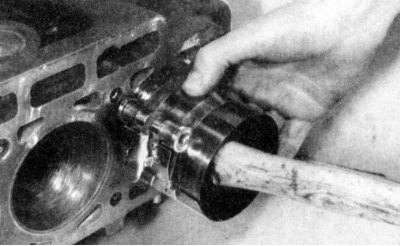
8. Lightly tap the piston bottom with a wooden hammer handle, while directing the end of the connecting rod toward the crankshaft journal. Working slowly, if you feel resistance as the piston moves through the cylinder, stop pressing immediately. Find what is interfering and eliminate the cause. Do not use force under any circumstances - you can break the ring and/or piston.
The piston rings can pop out of the compressor just before they enter the cylinder, so apply pressure to the compressor.
9. When the piston/connecting rod assemblies are installed, the bearing lubrication clearance should be checked before final tightening of the connecting rod cap bolts.
10. Cut a piece of plastic wire of the appropriate size, slightly smaller than the width of the connecting rod bearing, and place it on the journal of connecting rod No.1, parallel to the axis of the crankshaft.
11. Clean the bearing surface of the connecting rod cap, remove the protective tubes from the connecting rod bolts and install the connecting rod cap. Make sure that the mark on the cap matches the mark on the connecting rod.
12. Install the nuts and bolts and tighten to the torque specified in Table of sizes and adjustment data at the end of the manual. On M10 and M30 engines, achieve final thrust in three stages.
To avoid errors in measuring the tightening force, use a socket head with thin walls that will not jam between the connecting rod cap and the nut. If the head jams between the nut and the cap, lift the head slightly so that it does not touch the cap. Do not turn the crankshaft during this operation.
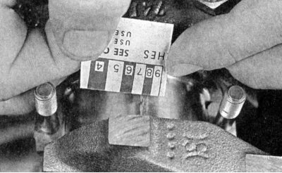
13. Loosen the nut and remove the connecting rod cover, being careful not to displace the plastic wire.
14. Compare the width of the flattened wire with the scale printed on the wire package. Compare the value with the requirements Size charts and adjustment data at the end of the manual to ensure the gap is correct.
15. If the clearance differs from the required one, the bearing shells may be of the wrong size (what does it mean to buy new liners). Before deciding whether to purchase different bearings, make sure there is no dirt or oil present when measuring the clearance between the bearings and the rods or caps. Also, re-measure the journal diameter. If the wire width was not uniform, the journal may be tapered (see section Checking the condition of the crankshaft).
Final installation of connecting rods
1. Carefully remove all traces of wire material from the journal and/or bearing surface. Be careful not to scratch the bearing surface - use your fingernail or the edge of a credit card to do this.
2. Ensure that the bearing surfaces are spotlessly clean, then apply an even coat of molybdenum disulphide grease or engine oil to both surfaces. You will need to push the piston into the cylinder to access the connecting rod bearing shell surface - first ensure that the connecting rod bolts, if used, have protective tubes fitted.
3. Slide the connecting rod back into place on the journal and remove the protective tubes from the connecting rod cap bolts. Install the connecting rod caps and tighten the nuts/bolts to the required torque.
4. Repeat the same procedure for the remaining pistons/connecting rods.
5. The following are important circumstances:
- During assembly, keep the outer surfaces of the bearings and the inner surfaces of the connecting rods and caps spotlessly clean.
- Make sure that the correct piston/connecting rod assemblies are installed in each cylinder.
- The notch or mark on the piston should face the front of the engine.
- Lubricate the cylinder walls with clean oil.
- When installing the connecting rod caps, lubricate the bearing surfaces after checking the lubrication clearance.
6. After all pistons/connecting rods are correctly installed, turn the crankshaft by hand several times to check for obvious binding.
7. Check the lateral play of the connecting rods (see section Removal the crankshaft).
8. Compare the measured lateral clearance with the requirements Size charts and adjustment data at the end of the manual to ensure that it is correct. If the backlash was correct before disassembly and the original crankshaft and connecting rods were installed, it should be retained. If a new crankshaft or new connecting rods were installed, the backlash may not be correct. If so, the connecting rods should be removed and sent to a machine shop for inspection.
This article is available at russian, bulgarian, belarusian, ukrainian, serbian, croatian, romanian, polish, slovak, hungarian
Article verified: Zhuravleva Isolda
Share information:
Previous articles
БМВ E28: Engine overhaul
Next articles
Similar articles on other types of BMW cars:
Checking the clearance between the bearings and the connecting rod… BMW 3 Series E21 (1975-1983)
Pistons and connecting rods — removal BMW 3 Series E46 (1998-2006, petrol)
Pistons and connecting rods — installation and checking of connecting… BMW 7 Series E32 (1986-1994)
Connecting electrical appliances BMW X3 E83 (2003-2010)
Pistons and connecting rods — design description BMW X5 E53 (1999-2006)
Link in different formats to this page
Visitor comments
No comments yet
- General information
- Governing bodies
- Manual
- Maintenance
- Power unit
- Engine repair
- Lubrication system
- Cooling system
- Ignition system
- Supply system
- Injection system (gasoline)
- Injection system (diesel)
- Exhaust system
- Transmission
- Clutch
- Car gearbox
- Front axle
- Rear axle
- Chassis
- Steering
- Brake system
- Wheels and tires
- Body
- Interior
- Exterior
- Heating system
- Electrical equipment
- Equipment and devices
- Power devices
- Windscreen wipers
- Electrical circuits
- General information
- Manual
- Maintenance
- Power unit
- Engine repair
- Ignition system
- Engine lubrication system
- Cooling system
- Fuel system (gasoline)
- Fuel system (diesel)
- Exhaust system
- Transmission
- Clutch
- Car gearbox
- Chassis
- Front and rear suspension
- Steering
- Brake system
- Body
- Exterior
- Interior
- Electrical equipment
- Heating system
- Equipment and devices
- Power devices
- Electrical circuits
- General information
- Manual
- Maintenance
- Power unit
- Engine in a car
- Engine overhaul
- Cooling system
- Supply system
- Ignition system
- Control system
- Transmission
- Clutch
- Manual gearbox
- Automatic gearbox
- Transmission line
- Chassis
- Steering
- Front suspension
- Rear suspension
- Brake system
- Body
- Body elements
- Car care and painting
- Electrical equipment
- Heater and air conditioner
- Equipment and devices
- Starter and generator
- Electrical circuits
- General information
- Operation and maintenance
- Specifications
- Power unit
- Engine repair
- Cooling and lubrication system
- Supply system
- Ecotronic power supply system
- Fuel injection system
- Ignition system
- Transmission
- Clutch
- Gearbox BMW 242/4
- Gearbox Getrag 262/8
- Gearbox Getrag 265/6
- Automatic gearbox
- Cardan gear
- Rear axle
- Chassis
- Steering
- Front suspension
- Rear suspension
- Brake system
- Electrical equipment
- Equipment and devices
- Electrical circuits