
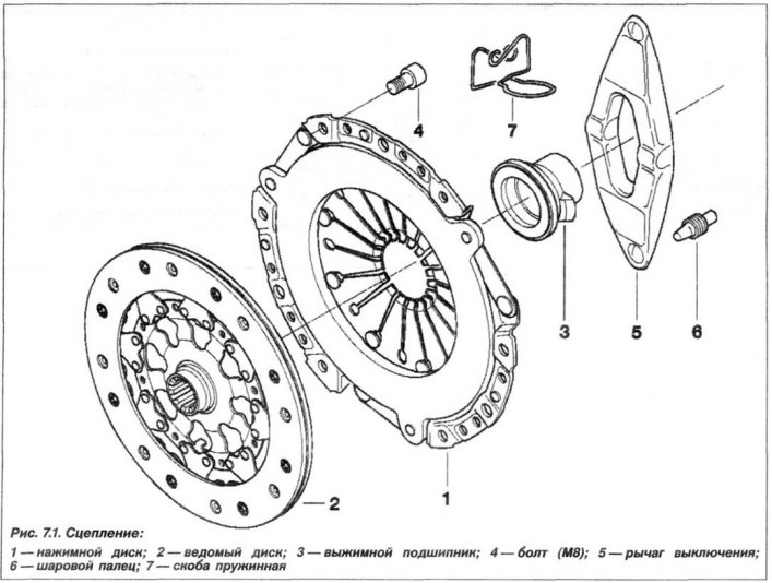
Structurally, the clutch consists of a clutch housing with a pressure plate (1, Fig. 7.1), driven disk (2) and the clutch release mechanism, which includes a release bearing (3), a release bearing lever (5), a ball pin (6) and a spring clip (7). The driven disk (2) is located between the pressure plate (1) and the flywheel.
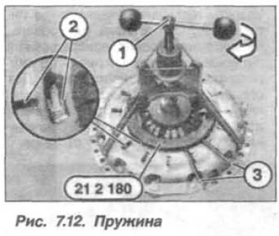
The distinctive features of the "SAC" type clutch are the presence of three sockets with stops for adjusting rings (see fig. 7.12).
The clutch housing with the pressure plate, called the "basket", is installed on the end (rear) surface of the flywheel on bolts that are tightened crosswise, in several steps, the final force depends on the engine model:
- bolts M8 (8.8) with a torque of 25 Nm (2.5 kgf·m);
- bolts M8 (10.9) with a torque of 34 Nm (3.4 kgf·m).
The driven clutch disc with an elastic hub has a splined connection with the primary (input) shaft of the manual gearbox (MT) and slides freely along it. Friction linings are installed on the disc surfaces using rivets; the minimum thickness of the disc lining is 7.5 mm. At the same time, the residual lining thickness between its surface and the rivet head must be at least 1.0 mm. The grade of the friction lining material is Textar T50 SM7. The disc hub has damping springs that provide shock absorption of the transmission during engine start-up and shutdown, during abrupt clutch engagement, as well as engine vibrations themselves, which guarantees a smooth drive (run) of the car. The driven clutch disc is centered with the primary shaft of the gearbox.
The clutch housing houses the clutch release lever. It is connected to a maintenance-free, self-centering release bearing.
As the driven disk linings wear, the pressure plate moves toward the flywheel, and the diaphragm spring sectors straighten. The hydraulic clutch drive (Fig. 7.2) does not require adjustment, since the amount of hydraulic fluid in the system automatically compensates for wear after each press of the clutch pedal.
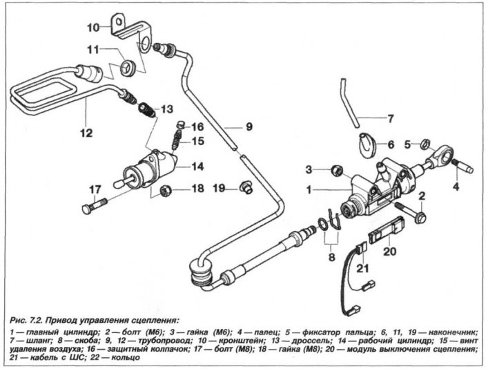
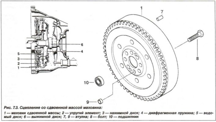
The design of the hydraulic clutch release drive is shown in Figure 7.2 and includes the main components - the master cylinder (1), pipelines (8, 12), hose (7) of the brake fluid feed tank, working (executive) clutch actuator cylinder (14), clutch switch module (20). On X5 vehicles, the engine flywheels are dual-mass (Fig. 7.3). One part (1) is connected to the crankshaft flange, the other part is connected to the clutch basket and is the working surface of the clutch mechanism. The friction surface can move, since between the flywheel parts there is an elastic element (2) of the spring type, which plays the role of a torsional vibration damper, in addition to which a friction torque limiter is used.
The maximum permissible end runout of the working surface of the driven disk is no more than 0.5 mm. For the pressure disk, the warping should be no more than 0.3 mm, the end runout relative to the diaphragm spring is no more than 0.6 mm, and the non-flatness (warping) flywheel surface under the driven disk in operation – no more than 0.2 mm.