
Fix the flywheel of the 6-cylinder engine with a tool «11.9.260» or flywheel 8-cylinder engine tool «11.9.263». Mark with a marker the relative position of the clutch basket on the flywheel.
Attention! Sudden release of the basket mounting bolts can break the diaphragm spring and dowel pins.
Remove the basket manually.
The polluted conducted disk is subject to replacement.
bolts (arrows, fig. 7.7) loosen the clutch basket fasteners sequentially, 1-1.5 turns crosswise, until the tension of the pressure plate is relieved. Loosen the bolts two or three turns and check that the cover does not get stuck on the dowel pins. Unscrew the bolts securing the basket completely and remove it.

Remove the clutch disc from the flywheel and wipe the end (working) flywheel surface.
Attention! Only wipe the clutch release bearing, but do not rinse.
The clutch test must be carried out in the following order.
Remove pad wear from housing, disc and flywheel surfaces using only a special cleaner or methyl alcohol. Carry out work in a respirator, because. the dust of the lining material is harmful to health.
Inspect the surfaces of the clutch pressure plate and flywheel for burrs, cracks, and heat spots.
Check the clutch disc for damage, wear and rust on the splines, replace the clutch disc if necessary.
Pay special attention to the riveted connections of the spring between the pressure plate and the casing. Clutches with damaged or loose rivets must be replaced.
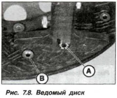
Measure the protrusion of the friction lining over the rivets for its fastening on the closing head (Ah, fig. 7.8), which must be at least 1.0 mm. The clutch disc with traces of grease and oils, with a reduced lining thickness, as well as with mechanical damage in the form of cracks, must be replaced.
The surface of the pressure plate is to be checked for warping with a metal ruler (timber) and probe. A pressure plate with an inward deflection of less than 0.3 mm can be used in further operation.
When installing a previously used driven disk, it must be checked for lateral runout, which should be no more than 0.5 mm. This is very important if there were comments on disengaging the clutch during its operation.
Examine the surface of the flywheel for scratches, cracks and colored spots (caused by local overheating). If necessary, grind the flywheel or replace it. Fasten the flywheel with bolts crosswise, with a torque of 120 Nm (12.0 kgf·m).
Attention! Do not clean the SAC clutch in pressure washers or washers.
Installing a slave drive to the primary (input) shaft of the manual transmission, check the grooves of the spline connection for signs of wear and the absence of signs of corrosion.
Inspect the diaphragm spring for signs of damage. Traces of working out the ends of the petals of the diaphragm spring are allowed to a depth of up to half of its thickness.
Check the input shaft bearing for ease of rotation and lack of runout. If necessary, remove the bearing with a puller «11.2.010» and install a new one.
Clean the friction linings of the pressure plate and the working surfaces of the pressure plate and flywheel with fine sandpaper.
Check the clutch release bearing by hand. It should rotate easily and make no noise. Particular attention should be paid to the bearing, which was noted for noise at the time of disengaging the clutch (pressing the pedal). Replace defective bearing.
Installation of the removed basket and clutch disc should be carried out in the reverse order, if necessary.
Remove traces of dust and oils from the working surface of the flywheel.
Clean the grooves of the hub from signs of wear and apply a thin layer of high-temperature anti-friction grease type «Molykote-Longterm2».
Check the presence and tight fit of the guide pins on the flywheel.
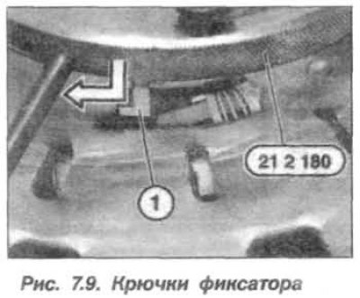
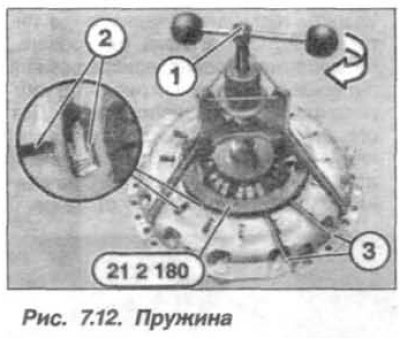
Note. Hooks (1, fig. 7.9) fixture lock «21.2.180» must fit into the clutch sockets.
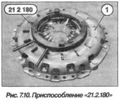
Position the clutch on a clean surface and install the tool on it «21.2.180» (pic. 7.10). Lock the clutch adjusting ring in its original position by squeezing the handles (1) to the stop and, holding them in this position, tighten the bolts (2) with rolled head. This operation should only be carried out on the previously installed clutch. The clutch adjusting ring is fixed in its original position.
Note. fixture «21.2.170» insert only into holes (arrows, fig. 7.11) for center pins.
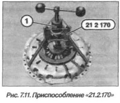
Install fixture «21.2.170» into the holes for the guide pins and tighten the nut (1, fig. 7.11) with rolled head.
Screw in the spindle (1, fig. 7.12) fixtures «21.2.170» until the diaphragm spring is fully compressed (2), while the handles (3) will start to rotate.
Attention! The driven disk is marked «Motorseit» (engine side) And «Getriebeseite» (manual transmission side). Inscription «Getriebeseite» must be visible during installation.
Do not touch the surface of the friction linings.
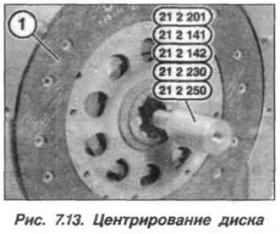
Install the clutch disc on the flywheel surface and center it using the tool «21.2.141» (S5D390Z), «21.2.201» (GS6–37BZ), «21.2.230» (GS6 53DZ/BZ) or «21.2.250» (GS6–17BG) (pic. 7.13).
When replacing the diaphragm spring, make sure that its petals are facing away from the flywheel.
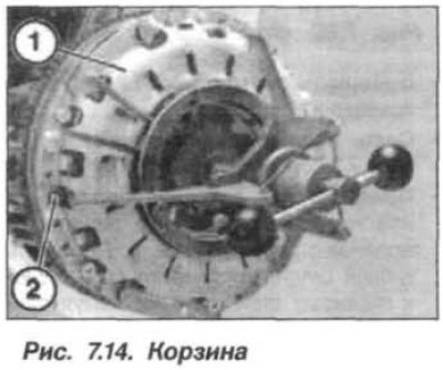
Install cart (1, fig. 7.14) flywheel clutch. At the same time, it should sit on the guide pins (2), and the installation marks match. Tighten the clutch mounting bolts by hand while holding the basket from moving so that the pressure plate is evenly pressed against the flywheel.
Attention! The pressure plate must be in full contact with the surface of the flywheel.
Remove excess anti-friction grease from the driven disc hub Tighten the clutch cover bolts in a criss-cross sequence, 1 to 1.5 turns each time, until the basket bolts are fully tightened to 25 Nm (2.5 kgf·m) for M8 bolts (8.8) or torque 34 Nm (3.4 kgf·m) – for M8 bolts (10.9).
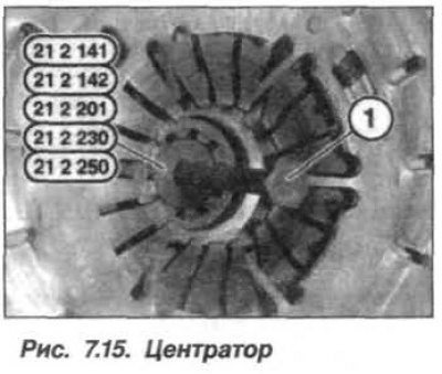
Remove the compression force from the diaphragm spring by turning the tool spindle «21.2.170». Loosen the knurled nut and remove the tool from the clutch. Loosen the thumbscrews and remove the tool «21.2.180» from clutch. Remove centering tool (centralizer) from the clutch disc using the supplied bolt (1, fig. 7.15) and flywheel retainer.
Lubricate the splines of the input shaft of the manual transmission with a thin layer of lubricant type «Microlube GL 261».
Check the condition of the release bearing and install it on the transmission.
Install manual transmission as described in section «Transmission».