
Remove brake fluid from the drive system reservoir using a syringe. Remove the rear part of the engine auxiliary protection panel in the area of the manual transmission.
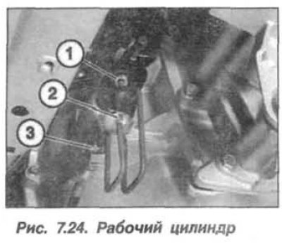
Clamp the flexible hose from the master cylinder to the reservoir using a special clamp "13.3.010". Unscrew the coupling (1, Fig. 7.24) fastening the hydraulic drive pipeline. Loosen the union (2) of the pipeline on the working cylinder and remove the hydraulic drive pipeline (3) together with the bracket.
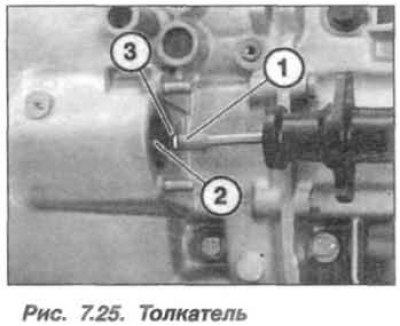
Unscrew the nuts (18, 2 pcs., see Fig. 7.2) fastenings of the working cylinder (14) and separate it from the manual transmission housing. The installation of the working cylinder should be carried out in the reverse order, while it is necessary to clean the outer surfaces of the working cylinder, the pusher (1, Fig. 7.25) and the mating plane with the clutch housing. Before installation, lightly lubricate the end (3) of the push rod (1) under the release lever with molybdenum grease of the type "Molykote Longtherm 2".
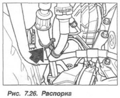
Correctly install the spacer (Fig. 7.26) between the fuel line and the hydraulic drive pressure hose.
Press the slave cylinder against the gearbox housing, tighten the new fastening nuts by hand and, tightening them alternately, tighten them to a torque of 22 N·m (2.2 kgf·m).
Tighten the union nut of the pressure supply pipe fitting to the working cylinder to a torque of 17 N·m (1.7 kgf·m).
Fill the brake fluid reservoir with brake fluid and bleed the hydraulic system as described above.