
Prepare the device "31.2.240/244/246" and remove the wheel. Disconnect the shock absorber and the rod from the ground clearance sensor (GDS) from the wishbone. Unscrew the nut (1, Fig. 13.17) the suspension arm hinge from the front axle beam and remove the bolt (forward). Loosen the nut (2) only three turns (three threads of thread), so that the transverse lever does not bounce back uncontrollably when pressed.
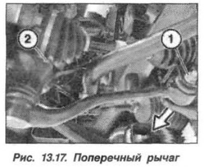
Using the puller "31.2.240" disconnect the transverse suspension arm from the pivot support. Unscrew the nut (2) completely and remove the transverse arm.
The installation of the front suspension wishbone should be carried out in the reverse order, and it is necessary, when installing the ball joint (2), to check the mounting points (cones) for traces of grease.
Place the washer under the new self-locking nut and tighten it to 80 N·m (8.0 kgf·m).
Connect the wishbone to the front suspension beam with a bolt, but first tighten the new self-locking nut.
Install the front wheels according to the pre-applied markings. Pre-tighten the bolts by hand.
Lower the vehicle onto its wheels, "shake it" and tighten the wheel mounting bolts crosswise to a torque of 140 N·m (14.0 kgf·m). Load the vehicle according to the diagram above.
If necessary, hold the unit from turning by the hexagon of the lever and tighten the nut securing the transverse lever to the front suspension beam in two steps:
- tighten to 100 Nm (10.0 kgf·m);
- turn 90° (±15°).
Check the geometric parameters of the front suspension, adjust the front wheel alignment angles.