
Attention! After completing the work on the front suspension beam, check the front wheel alignment angles.
Driving without a stiffening plate is prohibited.
Check the distance between the front side member and the dual cardan shaft.
Bleed the power steering.
Install plugs where pipelines are disconnected.
Removal of the front axle beam must be carried out in the following order.
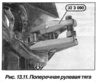
Prepare the device "32.3.090" and pump out the fluid from the power steering reservoir, dispose of the fluid.
Mark the relative position of the wheels on the hub and loosen the wheel mounting bolts. Raise the car on a lift and remove the front wheels. Remove the stiffening plate and the engine sump guard.
Open the engine compartment hood and install the slings of the lifting device on the engine. Hang the engine using the "00.0.200" device (see the section "Replacing the front axle gearbox").
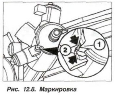
Set the steering gear to the middle position, with the markings (see fig. 12.8) on the steering shaft and steering gear must match. Remove the key from the ignition switch.
Remove the lower steering shaft clamp screw and disconnect the lower section of the steering shaft from the steering gear.
Loosen the nut using the puller "32.3.090", disconnect the transverse steering rod on the left and right from the steering knuckle (arrow, Fig. 13.11).
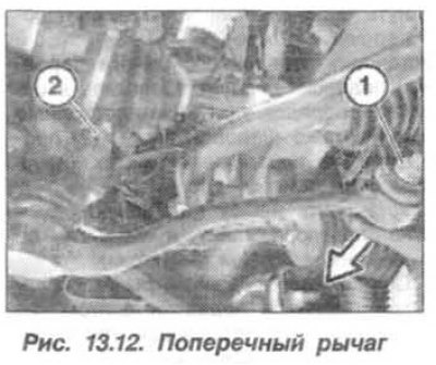
Loosen the nut (1) and remove the bolt (forward) Figure 13.12 and disconnect the suspension wishbone from the front axle beam on the left and right.
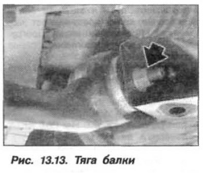
Unscrew the nut (arrow, Fig. 13.13), remove the bolt (forward) and disconnect the rod from the front axle beam on the left and right.
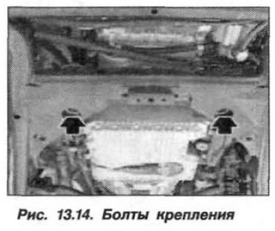
Disconnect the right and left engine mounts from the front axle beam. For a car with an M57 engine, additionally unscrew the upper nut of the engine mount/engine support bracket. Install a set of tools in the beam sockets. Unscrew the bolts (arrows, Fig. 13.14).
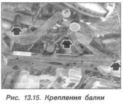
Place a garage jack under the front suspension beam and unscrew three bolts (arrows, Fig. 13.15) fastenings on the left and right of the beam and release it downwards.
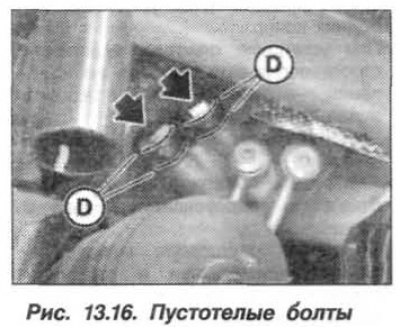
Slowly lower the beam until you have access to the hollow steering gear bolts (arrows, Fig. 13.16). Remove the hollow bolts and remove the front axle beam together with the steering gear.
The installation of the front axle beam should be carried out in the reverse order, while it is necessary.
If the threads in the front side member are damaged, repair them using spiral inserts. Replace the sealing rings (D, see Fig. 13.16).
Install the front suspension beam and tighten the new self-locking nuts on the bolts by hand.
Install the wishbones and rods onto the front suspension beam and pre-secure them using new self-locking nuts; do not tighten the nuts completely.
Install the engine and remove the support from underneath it.
Tighten the M14 hollow bolts of the power steering to a torque of 33 N·m (3.3 kgf·m).
Install the front wheels according to the pre-applied markings on dry, clean bolts, tightening them by hand beforehand. Lower the car onto the wheels, "sink" it and tighten the wheel mounting bolts crosswise to a torque of 140 N·m (14.0 kgf·m).
Tighten the new front suspension beam to side member self-locking nuts to a torque of 100.0 N·m (10.0 kgf·m).
Finally secure the longitudinal rod to the front axle beam with a new self-locking nut, tightening it to a torque of 165 N·m (16.5 kgf·m);
Finally secure the longitudinal transverse arm to the front axle beam with a new self-locking nut in two steps:
- first step – with a torque of 100 N·m (10.0 kgf·m);
- the second step is to turn it 90° (+15°).
When installing the tie rod, there should be no traces of grease on the seat cone or in the hole.
Install the tie rods and tighten the new nuts to a final torque of 80 N·m (8.0 kgf·m). If necessary, hold the unit from turning by the internal hexagon.
Tighten the new M8 nut (10.9) of the steel clamp of the steering gear to a torque of 24 N·m (2.4 kgf·m), the aluminum clamp – 28 N·m (2.8 kgf·m).
Adjust the front wheel alignment angles.
When installing the stiffening plate, strictly follow the process of its fastening - tighten the new bolts in two steps:
- 1st step, torque 56 Nm (5.6 kgf·m);
- 2nd step, turn to an angle of 90°.
Bleed the power steering.
Check the distance between the front side member and the double cardan shaft, which should be at least 5 mm (see section "Steering").