
Prepare the equipment "31.1.051", "31.1.052", "33.3.051", "33.3.052", "33.3.054" and "33.3.310".
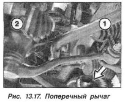
Unscrew the nut (1, see Fig. 13.17), remove the bolt (arrow) and disconnect the wishbone from the front axle beam. Secure the wishbone with a clamp or wire to prevent damage to the ball joint.
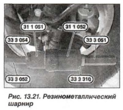
Using the devices "31.1.051", "31.1.052". "33.3.051", "33.3.052", "33.3.054" and "33.3.310" (fig. 12.21), press out the rubber-metal hinge from the wishbone.
Clean the parts thoroughly, there should be no traces of grease on the hinge and in the hole of the transverse lever. Clean the journal of the lever and apply an antifriction compound to it for pressing.
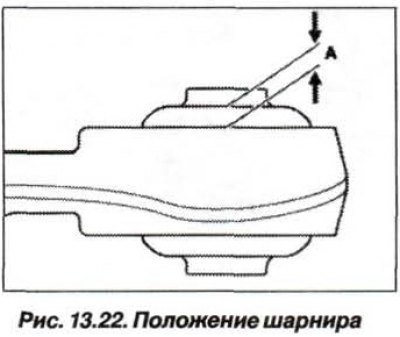
Using the devices "31.1.051", "31.1.052" and "33.3.054", press in a new rubber-metal hinge, paying attention to its correct position. It is installed from the side where the hole in the transverse lever has a chamfer. When installing, maintain the size of the protrusion "A" (fig. 13.22), which should be equal to 5.75±0.7 mm. Observe equal dimensions "A" of the hinge protrusion from the lever journal.
Install the lever on the suspension and wait about 30 minutes for the antifriction compound to evaporate, place the loaded vehicle on its wheels and tighten the new self-locking nut and bolt in two steps:
- 1st reception with a torque of 100 N·m (10.0 kgf·m);
- 2nd step: turn 90° (±15°).
Check and, if necessary, adjust the front wheel alignment angles.