
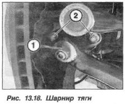
Prepare the equipment "31.2.240", "33.4.200" and "33.4.205". Remove the wheel and unscrew the nut (1, Fig. 13.18) tie rod to the pivot support. Loosen the bolts (2) securing the tie rod hinge to the pivot support. Press the front suspension tie rod hinge out of the pivot support.
If the front suspension tie rod joint sits too tightly in the pivot bearing, then it is necessary to install (screw) the "33.4.205" device onto the tapered journal and knock out the joint using the "33.4.200" impact puller.
Attention! A knocked out joint must be replaced.
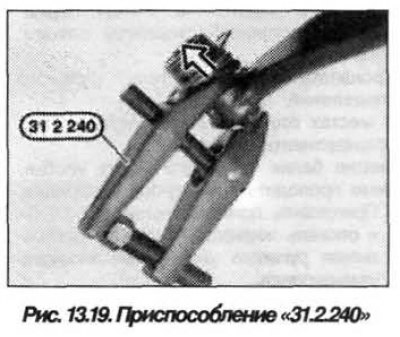
Tighten the nut a few turns to prevent the tie rod joint from flying out uncontrollably when pressing it out. Press out the suspension tie rod joint using the "31.2.240" tool (fig. 13.19) from the rod. Unscrew the nut and remove the joint from the front suspension rod.
The installation of the tie rod joint on the pivot support should be carried out in the reverse order, while it is necessary that there should be no traces of grease on the landing cone and in the hole.
Install a new self-locking nut (1, see Fig. 13.18) and tighten it to a torque of 80 N·m (8.0 kgf·m), if necessary, hold the unit from turning by the hexagon.
Replace the bolts (2) of the front suspension tie rod joint with new ones and tighten to a torque of 60 N·m (6.0 kgf·m).
Attention! Check the front wheel alignment angles.