
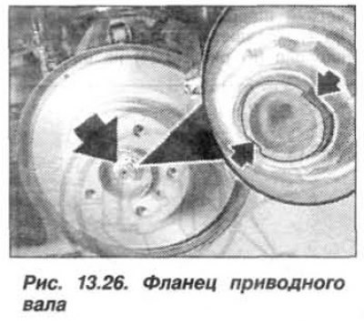
Caution! The flange nut is locked by tapping on the flat surfaces of the drive shaft of the drive wheel.
The replacement of the swivel support must be carried out in the following order. Remove the wheel, press the brake and lock its drive. Unlock and unscrew the nut (arrow, Fig. 13.26) with the flange fastening flange of the drive shaft. Loosen the screw (see fig. 11.27) brake disc mounts. Release the brake and remove the brake disc.
 |
 |
Remove the ABS/DSC wheel speed pulse sensor. Loosen the nut and press out the transverse steering rod from the swivel support using the puller "32.3.090". Loosen the tie rod hinge mounting bolts and remove the hinge from the swivel support.
Loosen the nut and, using the puller "31.2.240", disconnect the front suspension wishbone from the pivot support.
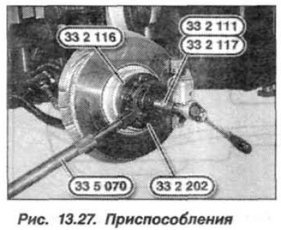
Install the fixtures "33.2.111", "33.2.116" and "33.2.117" using wheel bolts (1, Fig. 13.27). Support the swivel support with a jack.
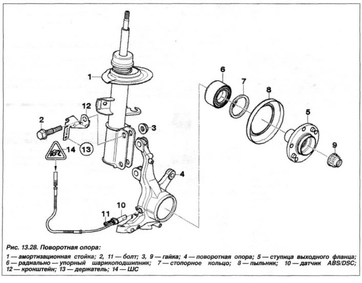
Press the wheel drive shaft out of the flange, holding it with a crowbar. Unscrew the nuts (3, Fig. 13.28) and remove the swivel support (4). Install the temporary bracket.
Attention! When removing the flange, the wheel hub bearing is damaged and is not suitable for further installation.
Clamp the swivel support in a vice with aluminum jaws, install the fixtures "33.2.116", "33.2.150" using wheel bolts on the flange and press out the flange using the "33.4.200" tool. If necessary, remove the inner retaining ring (7, Fig. 13.28) flange bearing.
Remove the dust seal (8) and brake mechanism protective cover and install them on the new pivot support. Install the new wheel hub bearing (6) in the pivot support.
The installation of the pivot support should be carried out in the reverse order, while it is necessary to tighten the new nuts (3) and bolts (2) securing the pivot support to the shock absorber strut to a torque of 250 N·m (25.0 kgf·m).
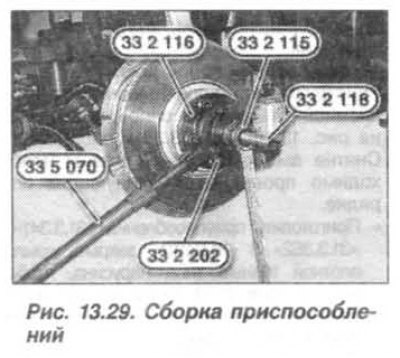
Lightly lubricate the splines of the drive shaft and insert the shaft into the splined flange. Install (screw) the device "33.2.118" into the drive shaft.
Install the fixtures "33.2.116", "33.2.150" using wheel bolts (1, Fig. 13.29) onto the flange and press the drive shaft using the device "33.2.115", holding it from turning with a crowbar.
When installing the transverse arm on the pivot support, it is necessary:
- make sure there are no traces of grease on the seat cone and in the hole;
- replace the self-locking nut;
- tighten the self-locking nut to a torque of 80 N·m (8.0 kgf·m).
Secure the tie rod joint to the pivot support with new bolts to a torque of 60 N·m (6.0 kgf·m).
When installing the transverse steering rod on the steering support, it is necessary:
- make sure there are no traces of grease on the seat cone and in the hole;
- replace the self-locking nut;
- if necessary, hold the unit from turning using the hex key;
- tighten the self-locking nut to a torque of 80 N·m (8.0 kgf·m).
Caution! If the tie rod end has a hole for installing a cotter pin, the self-locking nut is not installed.
Replace the flange nut, tighten it to 420 N·m (42.0 kgf·m) and lock it by tapping on the flat surfaces of the drive shaft of the drive wheel.
Check and, if necessary, adjust the front wheel alignment angles.
The original article is available on the website «bmwman.ru»