
Signs of damaged shock absorbers are:
- large amplitude of body vibrations;
- an increase in the amplitude of body vibrations when driving on a rough road;
- jumps of the car body when driving on a flat road;
- reversal of the car during braking, as one of the reasons;
- poor rut keeping and skidding of the car in a turn;
- extraneous noise, knocking when driving;
- increased tire wear.
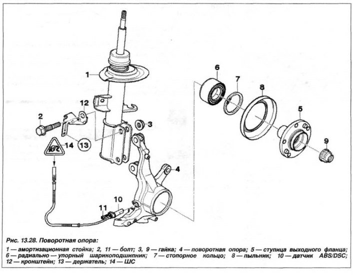
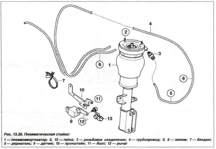
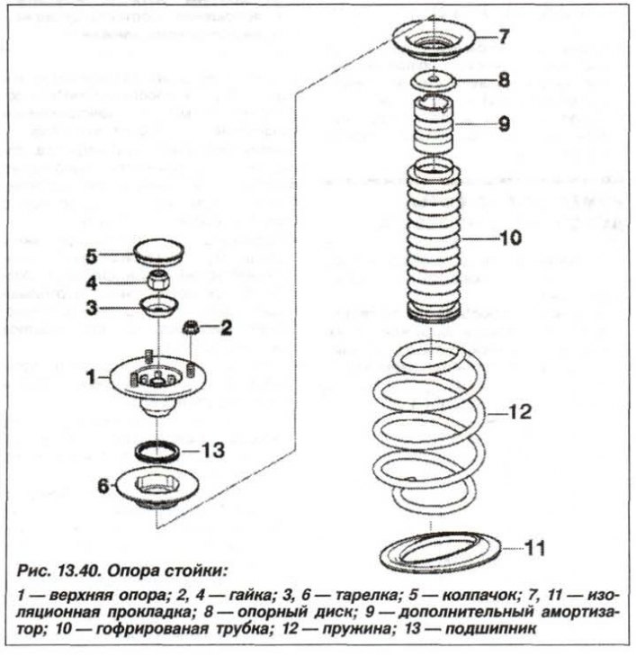
The design of the shock absorber and its support is shown in fig. 13.28, fig. 13.39 and fig. 13.40. Removal of an amortization rack is necessary for carrying out in a following order.
Prepare fixtures «31.3.341», «31.3.352» And «312.210», cover the wing with a thick cloth such as canvas, so as not to damage the paintwork. Remove the wheel, remove the stiffening plate and the engine compartment protection panels
Remove the brake caliper and secure it with a wire clip to the vehicle body, the lines remain connected. In case of disconnection, it is necessary to bleed the brake system.
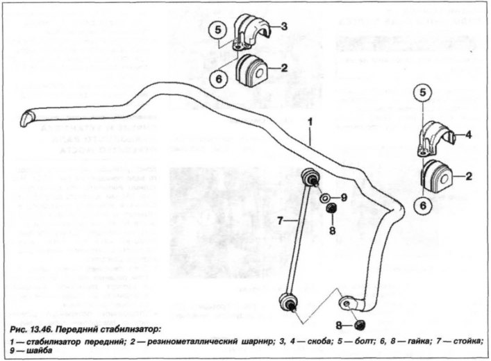
Loosen the nut (8, see fig. 13.46) rack mounts (7) anti-roll bar, when installing the suspension strut, tighten it to 100 Nm (10.0 kgf·m).
Remove from the holder the cable harness of the brake pad wear sensor and the wheel speed of the system «ABS» and undock the loop (2) above mentioned systems.
Mark the position of the studs in relation to the wheel housing. In this case, when installing the shock absorber, you can be sure that the camber will retain its value.
Attention! If there is no centering pin, then only one nut on the upper support of the suspension strut must first be unscrewed.
Loosen two nuts (2, see fig. 13.40) connection of the upper support of the suspension strut and the mudguard in the engine compartment.
Loosen the nuts (3, see fig. 13.28) connections of a shock-absorbing rack with a rotary support. Separate the swivel bearing and secure it with a wire clamp to the vehicle body. Loosen the remaining nut (or two nuts) connection of the upper support of the front suspension strut and mudguard. Move down, remove the suspension strut (1).
Attention! It is necessary to check the technical condition and operability of devices «31.3.341» And «31.3.352» before each use.
To avoid injury, do not use damaged attachments.
Do not make changes to the design of the devices.
Devices should only be used for their intended purpose.
Compress and decompress the device only with a manual wrench.
It is forbidden to compress the spring until the coils touch each other.
Clamp fixture «31.3.341» for the bar (1, fig. 13.41), in a vice.
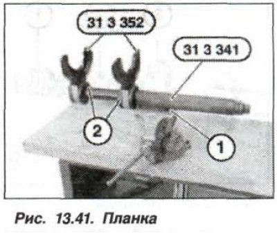
Install (horns) fixtures «31.3.352» (2) on the bar (1), by inserting them from the chamfer side of the plank. The locking pins of the horns should lock with an audible click and a sense of locking moment. Install the front strut in the compression tool, the coils of the spring should fully enter the recesses of the horns. Compress the spring with a hand wrench until the force is removed from the upper suspension strut support.
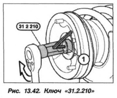
Removing the cap (5, see fig. 13.40) and loosening the nut (4) shock absorber top support only when the spring is properly compressed and its coils are completely in the recesses of the horns. If necessary, repeat the spring compression operation. holding knot (shock absorber rod) from turning with a wrench, unscrew the nut with a wrench «31.2.210» (arrow, fig. 13.42) and remove the shock absorber.
If a new spring is to be installed, the old spring must be completely dissolved (unclench), by unscrewing the tool «31.3.341» and removing it from the horns.
Install a new spring in the horns so that there are four turns of it between them. Check that the coils of the spring are completely located in the recess of the horns.
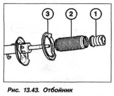
Replace fender if necessary (1, fig. 13.43). Check plate (2), insulating gasket (3) springs and the condition of the bellows. Make sure that the insulating gasket and spring plate are installed correctly.
Attention! In no case should the device be unclenched so that its horns (grips) rested against the upper and lower plates of the spring or against the extreme coil of the spring. Otherwise, the spring or fixture may be damaged.
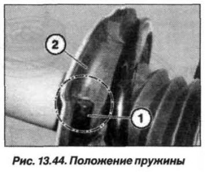
Installation of the suspension strut should be carried out in the reverse order, while inserting the suspension strut into the coil spring and the upper spring plate (pic. 13.44). The end of the spring must match the ledge of the lower plate or insulating gasket.
Screw on a new self-locking nut (4, see fig. 13.40) flush on the piston rod of the working cylinder of the shock absorber. Using the key «31.2.210», tighten the nut (M14) torque 64 Nm (6.4 kgf·m). Gently remove the compression force from the spring so that it is completely adjacent to the lower plate of the rack.
Tighten the nuts securing the upper support to the mudguard cup of the engine compartment to the following torque:
- with a rod diameter of 18 mm - 24 Nm (2.4 kgf·m);
- with a rod diameter of 21 mm - 34 Nm (3.4 kgf·m).
New self-locking nuts (3, see fig. 13.28) tighten the spring strut mounting bolts to 250 Nm (25.0 kgf·m).
Check the alignment angles of the front wheels and, if necessary, adjust them.