
Attention! When checking the ignition system, strictly observe safety requirements. The order of operation of cylinders 1-5-3-6-2-4. The voltage in the secondary winding of the ignition coils must be checked using the test adapter "12.7.040" in the following order. Prepare the devices "12.7.040", "12.7.041", "12.7.042", "12.7.043", "12.7.045", "12.7.046" and "12.7.050".
The following types of checks can be performed using the adapter kit:
- checking the voltage in the secondary winding of the ignition coil;
- comparison of ignition coils from different manufacturers;
- detect ignition coil defects;
- detect spark plug defects;
- identify faults in the fuel injection system.
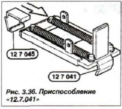
Connect the device "12.7.043" (connecting cable) with devices "12.7.041", which are intended for installation on ignition coils (Fig. 3.36).
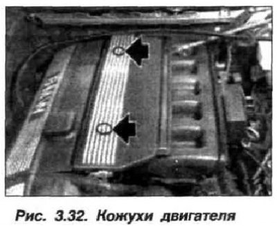
Remove the plugs (arrows, see Fig. 3.32), unscrew the bolts and remove the oil filler cap, remove the protective cover of the ignition coils and put the filler cap back in place.
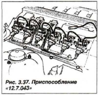
Install the "12.7.041" device on the ignition coils and connect it to the "12.7.043" device (Fig. 3.37).
Connect the DIS tester using the RZV connecting cable (static ignition distributor) to the last control adapter. Connect the DIS tester trigger clamp to the power supply wire of the ignition coil of the 1st cylinder.
Select the "Measuring system" and "Specified measurements" modes on the DIS and proceed according to the DIS System Manual. Analysis of oscillograms in the secondary target of the ignition system.
When working according to the instructions for the DIS-tester system, analyze the shape of the obtained oscillograms (Fig. 3.38), where:
- 1. — the beginning of the maximum value of breakdown voltage;
- 2. — the height of the ignition voltage amplitude;
- 3. — the height of the voltage amplitude on the spark plug electrodes;
- 4. — duration of spark discharge;
- 5. — voltage curve on spark plug electrodes;
- 6. — the beginning of the process of oscillation damping;
- 7. — damping of oscillations.
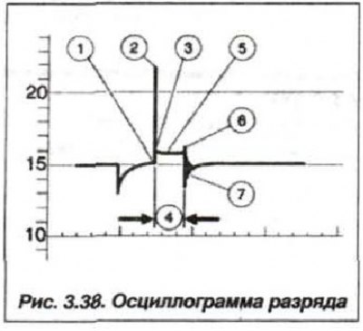
Note: When analyzing the oscillogram, it is necessary to take into account that the maximum value of the breakdown voltage (2) on the oscillogram is approximately 20-25% lower than its actual value.
The image of the processes in the secondary circuit of the engine ignition system in idle mode is shown on the oscillogram (Fig. 3.39), the pulses are arranged in the order of operation of the cylinders "1—5—3—6—2—4".
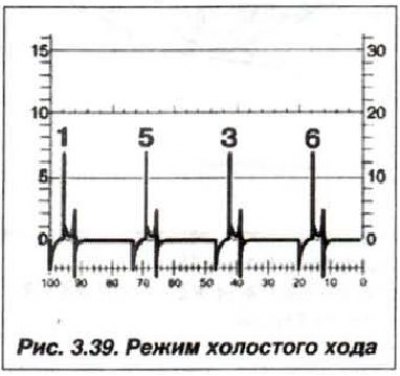
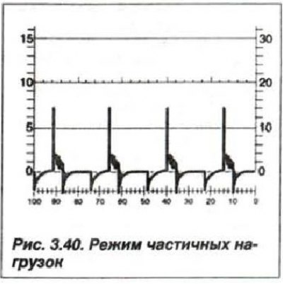
Much attention should be paid to the uniformity of the amplitudes in all cylinders; the permissible difference in values should not exceed 3000–4000 V. An image of the processes in the secondary circuit of the engine ignition system in partial load mode (2000 min⁻¹) is shown on the oscillogram (Fig. 3.40).
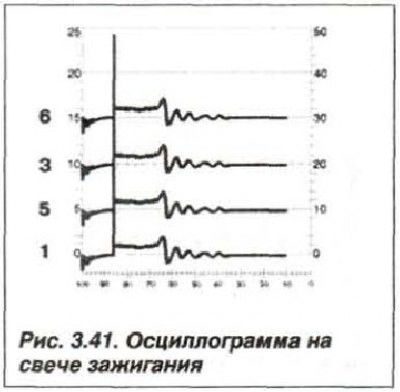
The analysis of the voltage curve on the spark plug electrodes and the attenuation processes in idle mode is shown in Fig. 3.41.
Pictures of possible malfunctions are easily read by comparing the obtained oscillogram with the oscillogram of a working ignition system (Fig. 3.42).
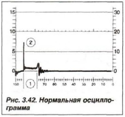
Normal spark discharge duration (1) and normal maximum breakdown voltage value (2) – the system is in good working order.
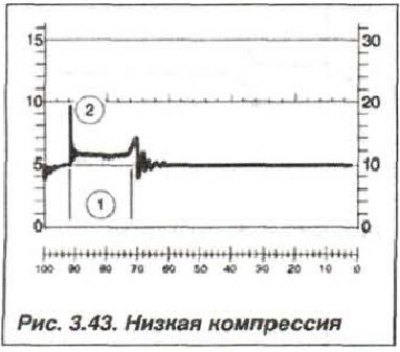
With a long duration of spark discharge (1, Fig. 3.43) and low amplitude of the maximum value of breakdown voltage (2) - the system is in good working order, but there is low compression in the engine cylinders.
Fluctuations in the duration of the spark discharge (1) indicate contamination of the spark plug.
Constant but reduced spark duration (1, Fig. 3.44) and a high amplitude of the maximum value of the breakdown voltage (2) indicate that there is damage to the high-voltage wires.
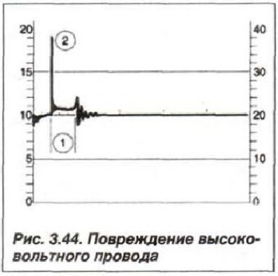
If the high-voltage wires are damaged, the voltage curve on the spark plug electrodes may be completely absent, and the maximum value of the breakdown voltage may increase sharply.
The reasons for too high ignition voltage may be:
- large gap between spark plug electrodes;
- high compression in engine cylinder;
- lean hot mix composition;
- low spark plug electrode temperature (cold candle);
- burnt spark plug electrodes;
- damaged high voltage wire.
Reasons for too low secondary ignition voltage may be:
- small gap between spark plug electrodes;
- low compression in engine cylinder;
- enriched hot mix composition;
- high spark plug electrode temperature (hot candle);
- new spark plug electrodes.