
If the installed boost air hoses are wet and have traces of grease, this may lead to turbocharger failure.
1. Disconnect the negative cable from the battery.
2. Remove the underbody trim.
3. Remove the upper radiator shroud and cover the generator to prevent contamination.
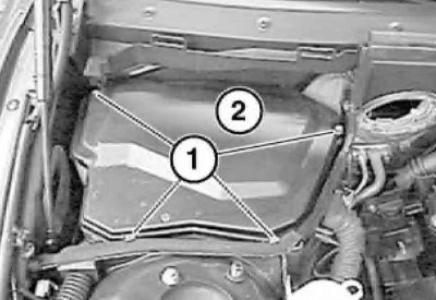
4. Remove the bolts (1) and remove the air duct (2).
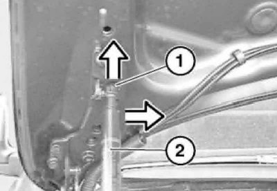
5. Remove the bolts (1) and remove the hose in the direction indicated by the arrow.
When installing, lubricate the working edges of the hose sealing rings with a thin layer of petroleum jelly.
6. Remove the corrugated hose (see illustration).
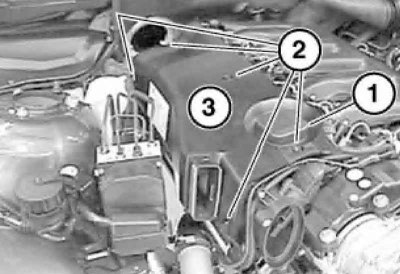
7. Remove the cover (1), unscrew the bolts (2) and remove the air cleaner housing (3).
8. Remove the air cleaner filter element.
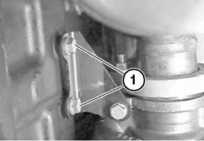
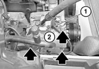
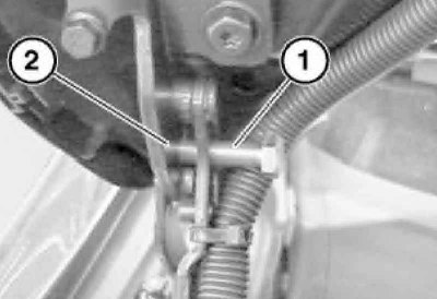
9. Remove the bolt (1) on the right bracket (2) of the engine support.
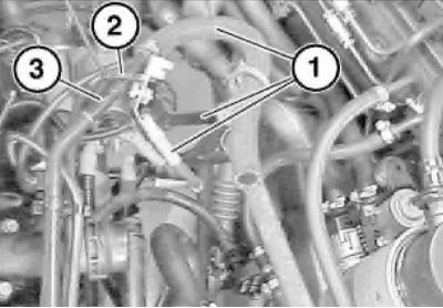
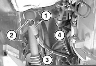
10. Loosen the clamp (1), remove the pipeline (2) of the boost air and immediately close the openings on the turbocharger.
11. Loosen the clamps (1) and remove the boost air hoses (2 and 3) together with the boost air line.
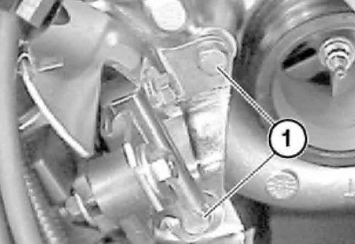
12. Unscrew the bolts (1) on the turbocharger. Remove the bracket of the pressure converter and the membrane mechanism of the vacuum regulator of the ignition advance.
13. Remove the drive belts (see section Replacing drive belts and their tensioners).
14. Disconnect the connector (1), unscrew the bolts on the turbocharger (2) and secure it to the side.
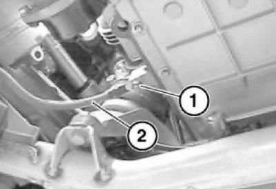
15. Remove the cooling system hose (1) together with the tank (2).
16. Remove the intake manifold (see section Removal and installation the intake manifold).
17. Remove the cooling system radiator (see chapter Engine cooling, heating, ventilation and air conditioning systems).
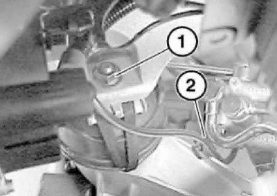
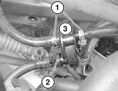
18. Loosen the nut (1) on the left engine mount bracket. Release the vacuum hose from the clamp (2) and disconnect the vacuum hose from the adapter below the clamp (2).
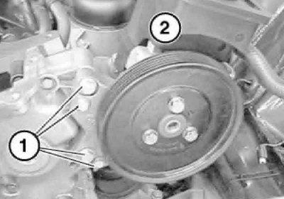
19. Unscrew the bolts (1) and secure the power steering pump (2) to the side.
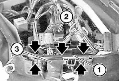
20. Cut the clamp (1), disconnect the branch (2) of the electrical wiring harness.
21. Remove the bolts (1) and cover (2) of the ECM compartment.
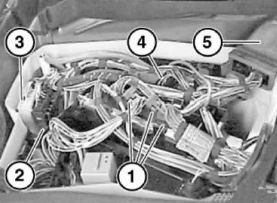
22. Release the clamps of the bar (1) and remove it by moving it upwards. Disconnect the connector (2) from the ECM. Remove the branch (3) of the electrical harness.
23. Disconnect connector (1) from ECM, disconnect connectors (2 and 3) and connector (4) of glow plug relay. Remove branch (5) of electrical harness from ECM compartment.
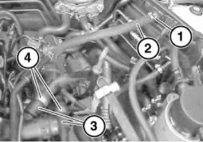
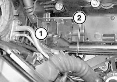
24. Loosen the clamp (1), disconnect the vacuum hose (2), press the clamps (3), disconnect the heater hoses (4) and secure them to the side.
25. Secure the vacuum hose, engine oil dipstick guide tube and positive battery cable (1) with a clamp (2) to the vacuum hose (3). Disconnect the fuel supply hose at the fuel filter assembly.
26. Disconnect the coupling (2) of the preheating valve (3) and set the valve aside.
The clamps (1) must not be loosened.
27. Support the hood, lift the clips (1) on both sides and slide them up. Disconnect the damper (2) from the hood on the left and right sides.
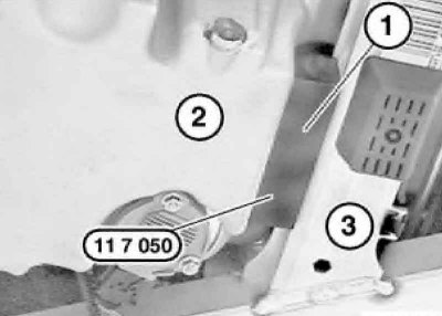
28. Screw two M8 bolts (1) into the hinges (2) of the hood, thus securing it.
29. Remove the cap (1) and loosen the nut (2). Release the positive battery cable (3) from the holder (4) and secure it to the engine.
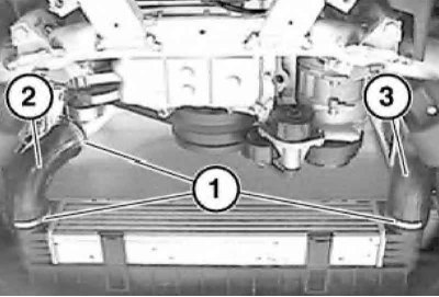
30. Install tool No.11 7 050 (1) between the engine oil pan (2) and the front axle beam (3).
31. Remove the catalytic converter (see chapter Exhaust systems).
32. Remove the manual transmission or AT (see chapter Manual gearbox and clutch or Automatic transmission).
33. Remove the nut (1), disconnect the ground wire (2) and set it aside.
34. Using a special lift, remove the engine upwards from the engine compartment by the front and rear eyes.
Be careful not to damage components in the engine compartment when lifting the engine.
35. Installation is performed in the reverse order of component dismantling. Make sure the support cushions are intact and replace them if necessary.
36. After installation, before starting the engine, check the levels of working fluids and adjust them if necessary.
37. Start the engine and check for fuel and fluid leaks, abnormal noises and vibrations.
38. Let the engine idle, then turn it off and check the fluid levels again.
[Examine the original source using the link on the website: bmwman]