Removal of the brake pads is identical for the entire system and must be carried out in the following order.
Prepare the devices "34.1.050" and "34.1.080". Tighten the parking brake and slightly loosen the wheel mounting bolts, front or rear, depending on the brake mechanism of the pads being replaced. Mark (with paint or marker) the relative position of the wheels, brake discs and wheel hubs.
Using a syringe, pump out some of the brake fluid from the reservoir. Raise the front (or back) part of the car, put it on stands and remove the wheels.
Mark (with paint or marker) the relative position of the brake pads in relation to the calipers, if these pads will be used in the future.
Caution! Always replace brake pads in pairs (4 pcs in a set.), even if the lining of only one shoe is worn out, and simultaneously on both front brake mechanisms (or rear) wheels. It is prohibited to swap the pads.
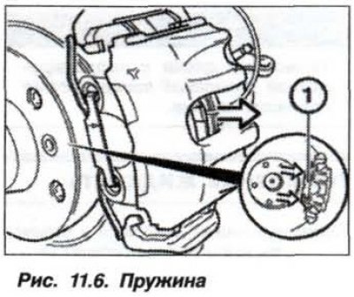
Remove the retaining spring (1, Fig. 11.6).
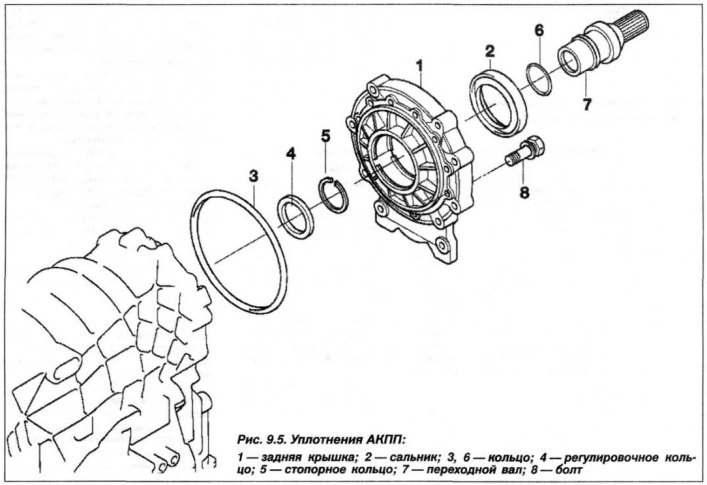
Disconnect the brake pad thickness sensor cable SS on the left caliper (arrow, Fig. 9.5) pressing the stopper. Pulling the wire is strictly prohibited. Remove the protective caps (5) of the guide pins using a screwdriver. Remove the brake hose from the holder.
Loosen the lower and upper guide pins (6) of the caliper using the "34.1.080" tool or a "7 mm" Allen key. Remove the caliper by moving it backwards. Secure the caliper to the car body with a wire clamp. Do not disconnect the brake hose; make sure that it is not stretched.
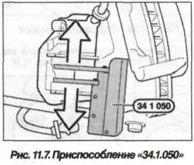
Using the device "34.1.050" (Fig. 11.7), move the piston as far as possible into the cylinder.
Attention! It is strictly forbidden to press the brake pedal when the brake pads are removed, as this will cause the piston to fall out of the caliper, the brake fluid to disappear and the system to become depressurized.
Monitor the brake fluid level.
Mark the pads to be removed.
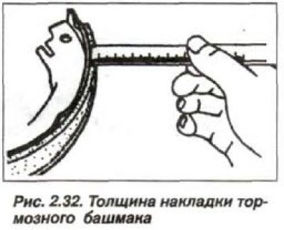
Check the thickness of the brake discs and the remaining thickness of the brake lining.
Do not apply grease to the rear plate of the pad.
The dust cap should not come into contact with the paste to prevent brake squealing.
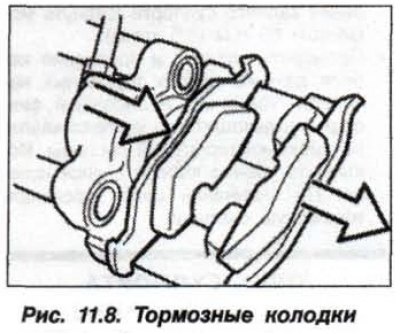
Remove the outer and outer brake pads (Fig. 11.8).
It should be noted that the inner brake shoe is attached to the piston by a petal spring.
The installation of the brake pads should be carried out in the reverse order, while it is necessary to clean the brake pads, work should be done in a respirator. Clean the guide surfaces and the places of installation of the pads in the opening of the housing with a soft metal brush and wipe with a rag soaked in alcohol.
Check the cleanliness of the working surfaces of the brake discs with your fingers. Warping, scratches and wear are not allowed. To remove them, grind the disc simultaneously from both sides so that its thickness meets the requirements of the Technical Specifications table.
Before installation, measure the actual thickness of the brake discs and brake pad linings. Brake discs with a gray or blue coating must be cleaned before installing new pads.
Check the wear sensor. If the contact plate insulation is worn out, the cable insulation is damaged or the plastic element is worn out, replace the sensor.
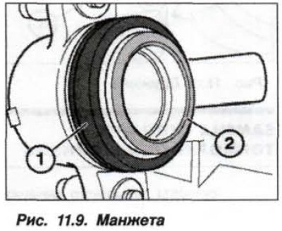
Check for cracks in the dust seal (1, Fig. 11.9) brake cylinder piston. A damaged seal must be replaced immediately, as penetrating dust causes leaks. The seal must be replaced by removing and disassembling the caliper at a service station. Clean the contact surface (2) of the brake cylinder piston and lubricate it with a thin layer of paste such as Plastilube to prevent squealing of the brake mechanism.
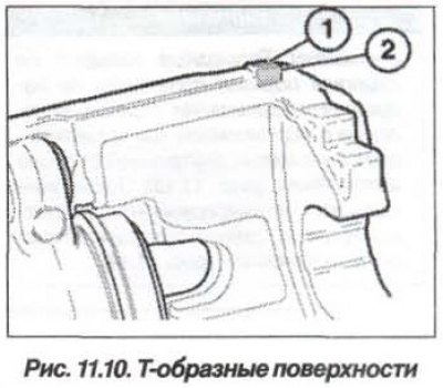
Clean the contact surfaces (1 and 2, Fig. 11.10) T-shaped ends of the brake pads and the caliper body, at the top and bottom, and lubricate them with a thin layer of paste to prevent squealing of the brake mechanism.
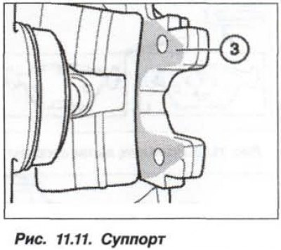
Clean the contact surface (3, Fig. 11.11) caliper of the disc wheel brake mechanism and lubricate it with a thin layer of paste to prevent squealing of the brake mechanism.
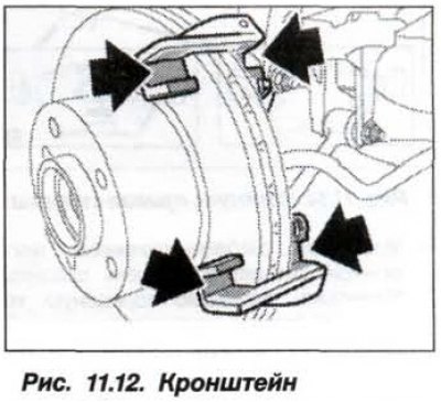
Clean the caliper bracket in the areas with T-shaped guides (arrows, Fig. 11.12) and lubricate them with a thin layer of paste to prevent the brake mechanism from squealing.
Install the piston in the caliper using a special device or a wooden or plastic mandrel, without distortions. In doing so, it is necessary to ensure that the piston surface and dust seal are not damaged, as well as the brake fluid level in the expansion tank and remove it in time with a bulb siphon. After changing the brake pads, the "MAX" mark on the brake fluid tank should not be exceeded.
Check (with two people) the ease of movement of the piston. Install a wooden block in the caliper, slowly press and release the brake pedal - the brake cylinder piston should easily come out and go back in. At the same time, the other brake mechanisms should be in working order. Repair the brake caliper at a service station.
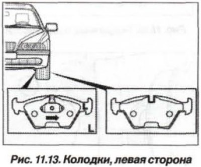
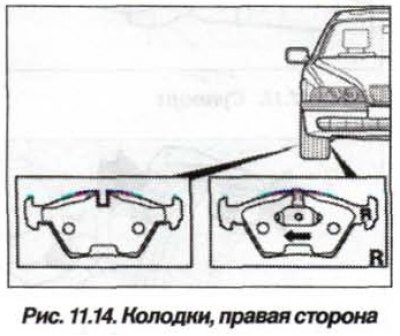
Attention! The brake pads on the piston side are tied in the direction of travel. The brake pad marked "L" is installed on the left, inner side of the car (fig. 11.13). The brake shoe marked "R" is installed on the right, inner side of the car (fig. 11.14).
 |
 |
Install the inner pad into the caliper piston using spring clamps. Install the outer brake pad into the caliper, with the pad facing the brake disc. The pads must be clean and fit precisely into the guides.
Clean and check the condition of the threads in the caliper and bracket. If necessary, clean the threads by running a tap through them. Set the caliper to the working position, insert serviceable and clean (without lubrication) guide pins and tighten them to a torque of 30.5 N·m (3.05 kgf·m) for the front and 28.0 N·m (2.8 kgf·m) for the rear.
Install protective caps into the guide pin holes. Connect the brake pad wear sensor to the cable harness. The wire must pass through the loop of the air bleed nipple cap. Install the brake shoe spring onto the caliper.
Caution! Press the brake pedal hard several times until you feel a strong resistance. This will cause the brake pads to take their working position.
Bleed the brake system. Install and temporarily secure (wrap by hand) wheel mounting bolts. After lowering the vehicle, tighten the wheel bolts crosswise to 140 N·m (14.0 kgf·m).
Check the tightness of the brake system bleeding nipples, connections for leaks, fluid leakage is not allowed. Check the brake fluid level and restore it to the "Max" mark.
Check the tightness of the brake system with the engine running. To do this, press the pedal several times with a force of 20-30 kgf and hold it for 10 seconds, the pedal should not sag.
Set the ignition key to position "1" and wait 30 seconds without starting the engine. This will erase the brake pad wear information from the ECU RAM. When driving with new brake pads, follow the above recommendations for their running-in.
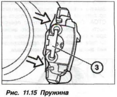
When replacing the brake pads on the rear wheel, the position of the retaining spring must be taken into account (fig. 11.15).