
Remove all pistons and drive disc (or flywheel). Check the crankshaft axial clearance. If the permissible axial clearance is exceeded (0.080–0.246 mm), replace the crankshaft thrust bearing liners.
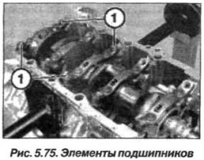
Turn away elements (1, Fig. 5.75) main bearing fastenings and unscrew the mounting pins (bushings). Sequentially loosen and unscrew the main bearing cap fastening bolts.
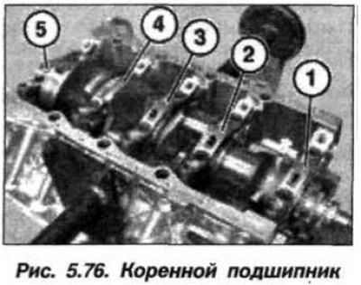
Check the marking of the caps (numbering in circles, 1–3); if there is none, apply it. The caps of main bearings 4 and 5 have no marking. The bearing cap is five-thrust. Remove the caps of the main bearings (1–5, Fig. 5.76). Remove the crankshaft and pay attention to its marking.
The crankshaft should be installed in the reverse order, and it is necessary to replace the crankshaft main and connecting rod bearing shells. Tighten the main bearing cap bolts (M10) in two steps:
- 1st – torque 20 N·m (2.0 kgf·m);
- 2nd – turn to an angle of 100°.
Do not wash off the coating of the bolts. Tighten the mounting pins (M8) and the main bearing cap fastening elements to a torque of 34 N·m (3.4 kgf·m).