- S, serial;
- B, 1st repair size;
- C, 2nd repair size.
The figures shown in the figure (2) indicate the classification of the bearings for the respective bearing beds 1-5 (main bearing caps), where 1 is yellow, 2 is green, 3 is purple.
Note. When replacing the main bearing shells or the crankshaft, the classification for the main bearing shells in the cylinder block is retained.
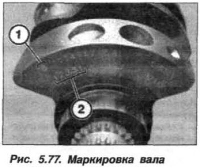
In accordance with the diameter of the main journals, the crankshaft has a yellow («Y»), green («G») or purple («V») marking.
The color marking of the liners in the main bearing caps must match the marking of the crankshaft.
Main bearing caps (1–3) are marked with embossed numbers. Bearing caps 4 and 5 are not marked.
The #5 main bearing cap can be identified by the surface for the thrust bearing half ring.
The letters shown in the figure (1, fig. 5.78) indicate the classification of the bearing shells for bearing positions 1-5 in the crankcase and are located on the side of the gearbox in the space between the cylinder banks.
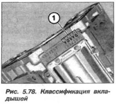
The first letter on the left indicates the first bearing seat at the front - yellow («Y»), green («G») or purple («V») marking.
Remove the old main bearing shells from the pastels of the crankcase. Install the main bearing shells with grooves for oil supply into the crankcase of the cylinder block. Unfasten the threaded pins (arrows, fig. 5.79) from main bearing caps.

Insert bearing shells without oil grooves into main bearing caps. Screw the hexagon socket dowels into the lugs of the main bearing cap. The half rings of the thrust bearing are installed in the crankcase of the cylinder block and in the main bearing cap. Half rings have grooves for oil supply.
Attention! Strictly ensure that the grooves of the thrust half rings are facing the crankshaft.
Install the thrust bearing half rings so that the oil supply grooves face the crankshaft webs. Align the thrust washers on the side of the main bearing cap. Thrust bearing cover No. 5 of the crankshaft has a groove. Inserts with a persistent collar (ledges) install in the grooves of the main bearing cap No. 5. Lay the crankshaft in the bed of the crankcase of the cylinder block.
When tightening the covers, in the process of checking the gap, use the old (filmed) bolts. The value of the angle of rotation of the bolt is determined using the fixture «00.9.120».
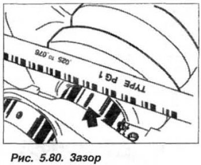
Remove the main bearing caps and measure the radial clearance in the main bearings directly on the shaft journal (arrow, see fig. 5.80) across the width of the flattened calibrated wire. When doing this, use the measuring scale of the wire packaging. The value of the radial clearance of the crankshaft bearings should be in the range of 0.024–0.052 mm.
If necessary, to adjust the clearance in the bearing, you should use new liners with a different color marking. Remove the gauge wire from the crankshaft journal using alcohol.
Lubricate the crankshaft journals and main bearing shells with engine oil. Install main bearing caps (1 – 5) so that the guide tabs of the inserts are on one side. Align the bearing caps with the bed along the side plane.
Blow out the blind holes with compressed air, the presence of moisture and contamination is not permissible. Use new main bearing cap bolts, do not wash off their coating. Install and hand tighten the main bearing bolts. Installed new main bearing cap bolts, tighten them to 20 Nm (2.0 kgf·m).
Loosen #5 thrust bearing cap fasteners. Tap the end of the crankshaft front and back with a mallet or plastic hammer to center the thrust bearing. Tighten the thrust bearing cap bolts (№5) torque 20 Nm (2.0 kgf·m). Tighten all bolts (M11) fixing the caps of the main bearings at a given angle - 100°, using a tool «00.9.120».
Check crankshaft axial clearance (see fig. 5.80), which should be within 0.080 - 0.246 mm. If the permissible axial clearance is exceeded, check and, if necessary, replace the thrust bearing shell, crankshaft and crankcase.
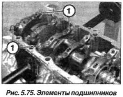
Tighten threaded bushings (M8) torque 6.0 Nm (0.6 kgf·m). Tighten all bolts (M10) fixing the main bearing caps at an angle of 100°. Replace bolts (1, see fig. 5.75) with a flange head and tighten them with a torque of 34 Nm (3.4 kgf·m).