
Raise the car, remove the wheels and the propeller shaft. Remove the wire retainer on the suspension arm, the left and right brake calipers, and secure them to the body with a wire clip. Remove the brake discs.
Remove the pulse sensors (right and left) wheel speed and disconnect the parking brake cable from the lever. Remove the heat shield over the propeller shaft and the gearbox ventilation pipe. Disconnect the brake pad wear sensors from the ground clearance sensor.
On a vehicle with an air spring, remove the air supply system fuse to prevent it from being triggered. Loosen the pipes to the manifold to relieve pressure in the system.
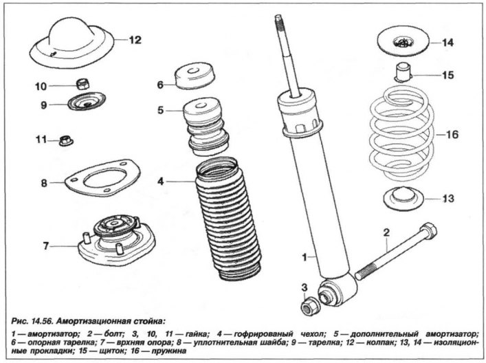
Remove the bolts (2, see Fig. 14.56) and disconnect the shock absorbers (1) from the swing arms.
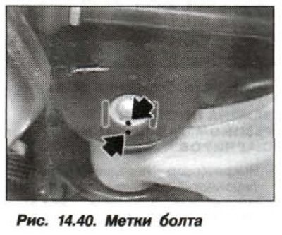
Support the beam (1, Fig. 14.40) rear axle with a jack "00.2.030/040" and adaptation "33.4.221/226".
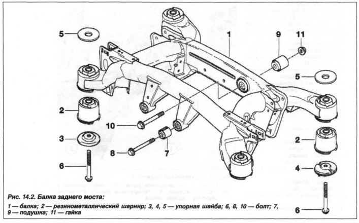
Remove the left and right bolts (6, see Fig. 14.2) and carefully lower the beam (1) of the rear axle. Check the condition of the beam, damaged threads on the body side can be repaired using inserts made of threaded spiral (M12x14x18), while the insert should not protrude from the thread being repaired.
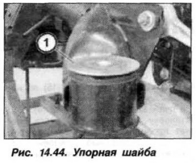
The installation of the rear axle beam assembly should be carried out in the reverse order, while it is necessary to apply a thrust washer (1, Fig. 14.44) on four rubber-metal hinges.
Thrust washers with studs (4, see Fig. 14.2) must be installed from below the beam, while the thrust washer studs must be located parallel to the vehicle axis.
When installing the beam, its lug must enter the socket of the hole in the hinge support and be secured with a locking bracket.
New bolts (M14x1.5x138) tighten the beam fastenings to the car body gradually, crosswise, with a final torque of 163 N·m (16.3 kgf·m). Turn on the air spring pump.
On a car with a spring spring, all operations are carried out in the same way, but it is necessary to remove the coil spring and shock absorber.
[This article is based on data from the website «BMWman.ru»]