
Attention! Upon completion of the installation of the steering column, you must:
- perform steering angle correction for dynamic stability control (DSC);
- check the freedom of movement of the steering column over the entire range of adjustments in relation to neighboring parts and pipelines;
- check the operation of mechanical devices (ignition lock cylinder, steering wheel lock, interlock system) and electrical systems.
Removing the steering column assembly must be carried out in the following order. Disconnect «–» terminal from AB.
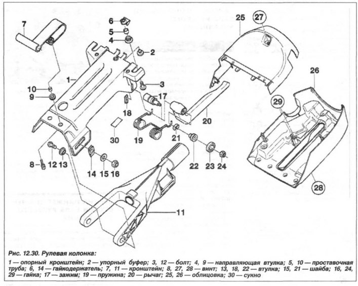
Remove bolts (28, fig. 12.30) fixing the bottom trim panel (26). Disconnect the horn loop and OBD loop. Remove the instrument panel trim, steering wheel, upper and lower steering column trim.
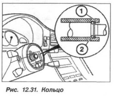
Remove the ring from the groove (1, fig. 12.31). If necessary, disconnect the interlock linkage from the steering wheel lock. Unscrew the mounting bolts, disconnect the loops and remove the switch brackets from the steering column.
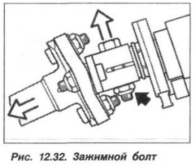
Loosen the nut (dark arrow, fig. 12.32) and remove the clamp bolt. Move the steering shaft downward (left, light arrow).
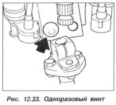
Cut off the head of a disposable screw with a chisel (arrows, fig. 12.33). Disconnect from the holders all the wires leading to the steering column. Unscrew the screw and release the latch, disconnect the loop from the ignition switch.
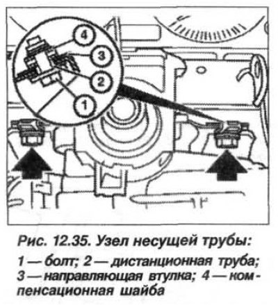
Remove screws (3, fig. 12.34) mechanical adjustment unit. Remove bolts (1, arrows, fig. 12.35) carrier tube and remove the steering column.
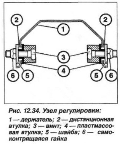 |  |
Installation of the steering column should be carried out in the reverse order, while it is necessary to replace the self-locking nuts (6, see fig. 12.34) and tighten them to 8.0 Nm (0.8 kgf·m). The inner surface of the sleeve (4) grease lightly.
Install the remote tube, tighten the one-time screw until it breaks at the neck. The clamping screw must enter the socket on the steering shaft, replace the self-locking nut and tighten it to the torque:
- on steel connection - 24 Nm (2.4 kgf·m);
- on an aluminum alloy connection - 28 Nm (2.8 kgf·m).
Pay attention to the position of the ring (1, see fig. 12.31) in relation to the snap ring (2).