
Table of contents: Removal ↓ Installation ↓
- Home
- BMW 5 Series
- E28
- Power unit
- Engine in a car
- Removal and installation the cylinder head
Removal and installation the cylinder head (BMW 5 Series E28)
Removal
1. Relieve the fuel pressure on all engines with a fuel injection system (see chapter Power supply system).
2. Disconnect the negative battery cable. Where the battery is located in the engine compartment, it can be completely removed from the vehicle (see chapter Ignition system).
If your vehicle's radio is equipped with an anti-theft system, make sure you enter the correct code before disconnecting the battery.
If the instrument cluster displays the wrong language after connecting the battery, refer to Section Anti-theft audio system and instrument cluster language, which describes the procedure for installing the required language.
3. Remove the air cleaner assembly (see chapter Power supply system).
4. Disconnect the wiring from the ignition distributor (if necessary, first mark the location of all wires) and the high-voltage wire from the ignition coil (see chapter Ignition system).
5. Disconnect the wire from the coolant temperature sensor unit (see chapter Cooling system).
6. Disconnect the fuel supply lines from the fuel rail or carburetor, as provided (see chapter Power supply system).
7. Drain the cooling system (see chapter Cooling system).
8. Clearly mark and then disconnect all remaining hoses from the throttle body, intake manifold, carburetor and cylinder head as provided.
9. Disconnect the exhaust manifold from the cylinder head (see section Removal and installation the exhaust manifold). Depending on the type of engine, you may not have to disconnect the manifold from the exhaust pipe; however, on right-hand drive models, the steering column intermediate shaft may block access to the cylinder head lash adjustment screws.
10. Disconnect all remaining hoses and tubes from the intake manifold, including the spark advance vacuum lines, as well as the heater and cooling system hoses.
11. On early carbureted models, disconnect the wiring from the generator and starter.
12. Remove the intake manifold (see section Removal and installation the intake manifold). Do not disassemble or remove any components of the fuel injection system unless absolutely necessary.
13. Remove the fan drive belt and the fan itself (see chapter Cooling system).
14. Remove the cylinder head cover and its gasket (see section Removal and installation the cylinder head cover). Remove the semi-circular rubber seal from the front of the cylinder head where it is not integrated into the cover gasket.
15. Bring piston No.1 to the TDC position of the compression stroke (see section Bringing the piston of the first cylinder to the top dead center (TDC) position).
16. Remove the timing belt or chain (see section Removal, inspection and installation of the timing chain and its tensioner sprockets or Replacing the front oil seals).
If you want to save time removing and installing the timing belt or chain and retiming the engine, you can disconnect the camshaft sprocket and hang it off to the side with a piece of rope without removing the chain or belt. The rope should keep the chain or belt taut so that it cannot slip off the sprockets.
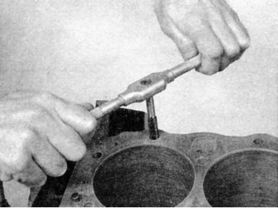
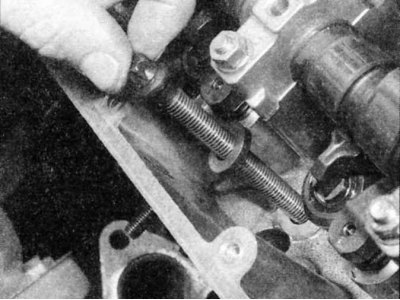
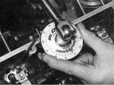
17. Loosen the cylinder head bolts gradually, a quarter turn at a time, in the reverse order of tightening (see photo 6, 7, 8, or 9). On engines M10, M20 and M30 this time do not disassemble or remove rocker arm assembly.
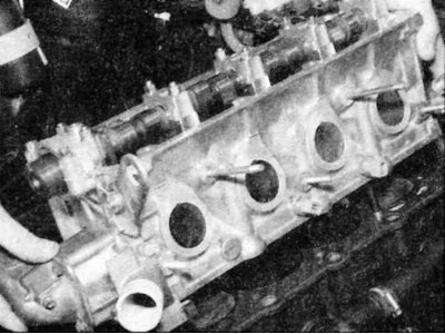
18. Remove the cylinder head by lifting it straight up off the engine block. Do not insert anything between the cylinder head and the engine block, as this may damage the gasket sealing surfaces. Instead, place a blunt rod into the entry hole to gently pry the head free.
19. Remove all remaining external components from the head to allow for a thorough cleaning and inspection. The cylinder head servicing procedure is described in Section Engine Component Overhaul Procedures. On M40 engines, remove the rubber sealing ring from the groove in the top of the oil pump housing/front cover.
Installation
1. When installing the cylinder head, the mating surfaces of the head and cylinder block must be absolutely clean.
2. Use a scraper to remove all traces of carbon and old gasket material, then clean the mating surfaces with a suitable solvent. If there is oil on the mating surfaces when the head is installed, the gasket will not seal properly and leaks may occur. When working on the cylinder block, pack the cylinders with clean rags to prevent dirt from getting into them. Remove any remaining material that gets into the cylinders with a vacuum cleaner.
3. Check the mating surfaces of the head and block for nicks, deep scratches and other damage. If the damage is minor, it can be removed with a file; if they are serious enough, then only mechanical treatment can correct them.
4. Using a suitable size tap, go over the threads in the head bolt holes, then clean the holes with compressed air - make sure there is nothing left in the holes (including oil, water, etc.).
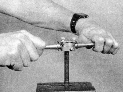
5. BMW experts recommend replacing the head bolts, but if you still use old bolts, clamp each one in a vice and go over it with a die. To remove traces of corrosion and restore the threads. Dirt, corrosion, traces of sealant and damaged threads affect the tightening force readings of the bolts.
6. If the bolts or their threads are damaged, use new bolts.
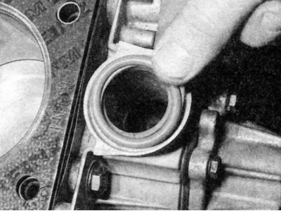
7. Reinstall all components removed from the head prior to cleaning and inspection. On M40 engines, install a new O-ring in the groove in the top of the oil pump housing/front cover.
8. Make sure that the sealing surfaces of the gasket between the cylinder block and the head are clean and free of grease. Install the head gasket on the block with the side indicated by the manufacturer facing up (usually it says "UP", "OPEN" or something similar). Use the mounting pins at the top of the unit to properly position the gasket.
9. Carefully install the cylinder head onto the block. Use the guide pins for proper alignment.
10. On models where the engine is slightly tilted (for example, the M40 engine), It may help to install guide rods to more accurately align the head position on the block. To do this, use two old head bolts screwed into each end of the block. Cut the heads off the bolts and use a hacksaw to cut slots in the tops of the bolts so that they can be removed after the cylinder head is installed.
11. Install the cylinder head bolts.
12. Tighten the head bolts in the sequence shown below to the specified torque.
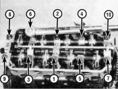
TIGHTENING sequence of cylinder head bolts for M10 four-cylinder engines.
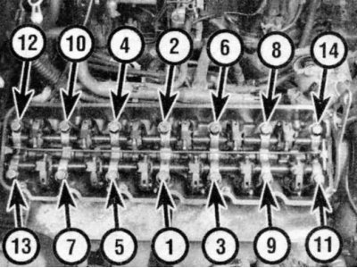
TIGHTENING sequence of cylinder head bolts for M20 six-cylinder engines.
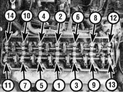
TIGHTENING sequence of cylinder head bolts for M30 six-cylinder engines.
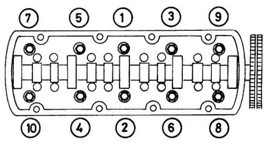
TIGHTENING sequence of cylinder head bolts for M40 four-cylinder engines.
13. Please note that on some engines the final tightening stage occurs after the engine has been running.
14. Perform the rest of the installation in the reverse order of removal. On M10, M20 and M30 engines, adjust the valve clearances before installing the cylinder head cover (see chapter Routine car maintenance) - check them again after the engine has warmed up. Start the engine and check for leaks.
This article is available at russian, bulgarian, belarusian, ukrainian, serbian, croatian, romanian, polish, slovak, hungarian
Article verified: Zhuravleva Isolda
Share information:
Previous articles
БМВ E28: Engine in a car
Next articles
Similar articles on other types of BMW cars:
Removal and installation the cylinder head BMW 3 Series E30 (1982-1994)
Removal and installation the cylinder head. Models 318is, 318ti BMW 3 Series E36 (1990-2000)
Cylinder head of gasoline engines of the M52 series — removal and… BMW 7 Series E32 (1986-1994)
Removal and installation cylinder head covers BMW 7 Series E38 (1994-2001)
Removal and installation the cylinder head BMW X3 E83 (2003-2010)
Removal and installation the lock cylinder BMW X5 E53 (1999-2006)
Link in different formats to this page
Visitor comments
No comments yet
- General information
- Governing bodies
- Manual
- Maintenance
- Power unit
- Engine repair
- Lubrication system
- Cooling system
- Ignition system
- Supply system
- Injection system (gasoline)
- Injection system (diesel)
- Exhaust system
- Transmission
- Clutch
- Car gearbox
- Front axle
- Rear axle
- Chassis
- Steering
- Brake system
- Wheels and tires
- Body
- Interior
- Exterior
- Heating system
- Electrical equipment
- Equipment and devices
- Power devices
- Windscreen wipers
- Electrical circuits
- General information
- Manual
- Maintenance
- Power unit
- Engine repair
- Ignition system
- Engine lubrication system
- Cooling system
- Fuel system (gasoline)
- Fuel system (diesel)
- Exhaust system
- Transmission
- Clutch
- Car gearbox
- Chassis
- Front and rear suspension
- Steering
- Brake system
- Body
- Exterior
- Interior
- Electrical equipment
- Heating system
- Equipment and devices
- Power devices
- Electrical circuits
- General information
- Manual
- Maintenance
- Power unit
- Engine in a car
- Engine overhaul
- Cooling system
- Supply system
- Ignition system
- Control system
- Transmission
- Clutch
- Manual gearbox
- Automatic gearbox
- Transmission line
- Chassis
- Steering
- Front suspension
- Rear suspension
- Brake system
- Body
- Body elements
- Car care and painting
- Electrical equipment
- Heater and air conditioner
- Equipment and devices
- Starter and generator
- Electrical circuits
- General information
- Operation and maintenance
- Specifications
- Power unit
- Engine repair
- Cooling and lubrication system
- Supply system
- Ecotronic power supply system
- Fuel injection system
- Ignition system
- Transmission
- Clutch
- Gearbox BMW 242/4
- Gearbox Getrag 262/8
- Gearbox Getrag 265/6
- Automatic gearbox
- Cardan gear
- Rear axle
- Chassis
- Steering
- Front suspension
- Rear suspension
- Brake system
- Electrical equipment
- Equipment and devices
- Electrical circuits