Attention! When carrying out work, maintain absolute cleanliness. Do not allow the system to become clogged. Seal disconnected pipelines and their installation sites with caps/plugs.
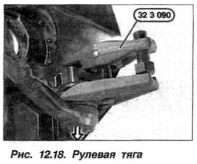
The replacement of the power steering gear must be carried out in the following order. Prepare the device "32.3.090", using a clean syringe, pump out the fluid from the reservoir (tank) of the power steering and dispose of it.
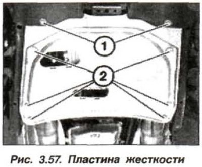
Remove the front wheel, remove the engine sump guard panel and, if necessary, the engine compartment auxiliary mechanism screen. Remove the stiffening plate. Unscrew the nut on the engine support bracket on the left and right.
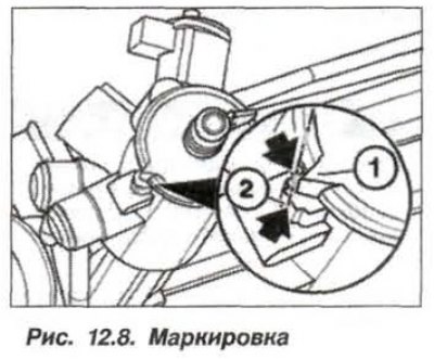
Raise the engine using the "00.0.200" tool (see the "Engine" section). Set the steering gear to the straight-ahead position, with the marking on the cap (1, see Fig. 12.8) and on the body (2) must match. In this position, remove the key from the ignition switch and lock the steering wheel.
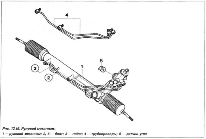
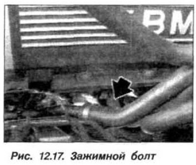
Remove the lower clamping bolt (M8) of the dual cardan shaft (arrow, Fig. 12.17). Unscrew the bolts M12x1.5x75 (arrows, see Fig. 12.15) fastening the steering gear to the front axle beam. Remove the dual cardan from the steering gear shaft.
 |
 |
Loosen the nuts securing the tie rod ends (right and left) to the swivel bearings. Using a puller (device "32.3.090"), press out the right and left transverse steering rods (arrow, Fig. 12.18).
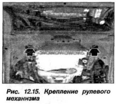
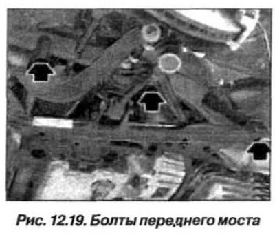
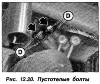
Support the front axle beam with a garage jack and remove the bolts (arrows, Fig. 12.19) and lower the jack. Remove the heat shield, unscrew the hollow bolts (arrows, Fig. 12.20) and remove the steering mechanism, moving it to the left side.
 |
 |
The installation of the steering mechanism should be carried out in the reverse order, while it is necessary.
Replace the sealing rings (D, 4 pcs.) of the hollow bolts (M14) and tighten the bolts to a torque of 33 N·m (3.5 kgf·m), and the hollow bolts (M16) to a torque of 39 N·m (3.9 kgf·m).
Tighten new bolts (M12, 10.9) securing the front axle to the side member to a torque of 100.0 N·m (10.0 kgf·m).
Tighten the new self-locking nuts securing the tie rod end to a torque of 80 N·m (8.0 kgf·m), while there should be no traces of grease on the seat cone of the end and in the hole. If necessary, hold the unit from turning by the internal hexagon.
Check that the marks on the steering gear shaft and the steering shaft match (see fig. 12.8).
Tighten the bolt (M8) of the steel dual cardan shaft to a torque of 24 N·m (2.4 kgf·m) or to a torque of 28 N·m (2.8 kgf·m) if it is made of aluminum alloy.
Check the distance between the front side member and the dual cardan shaft.
Replace the self-locking nuts (M12, 10.9) securing the steering gear and tighten them in three stages – to a torque of 100 N·m (10.0 kgf·m) + 50 N·m (5.0 kgf·m) + turn further by an angle of 90°.
Fill the reservoir with fluid, bleed the power steering and restore the working fluid level.
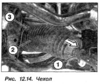
Check and adjust the front wheel alignment angles. To do this, loosen the lock nut (1, see Fig. 12.14) transverse steering rod on the left and right sides. Adjust the wheel alignment by turning the transverse steering rod by the hexagon (2).
Install the stiffening plate (see fig. 3.57) and tighten the bolts of its fastening in two stages: tighten with a torque of 56 N·m (5.6 kgf·m) + turn further by an angle of 90°.