
Note: This is a complex operation. Read this entire paragraph before attempting it. Make sure you have a lifting device, jack, and supports of sufficient load capacity. Take notes during disassembly so that the routing of wires and hoses, the location of brackets, and other "little things" do not cause you any difficulties during assembly.
Removal
1. Remove the hood as shown in chapter 11.
2. Relieve the pressure in the fuel system (see chapter 4A). Disconnect the negative cable from the battery (see chapter 5A)
3. Drain the coolant (see chapter 1).
4. Drain the oil from the engine (see chapter 1).
5. Separate from the engine and remove the manual gearbox (see chapter 7A) or automatic transmission (see chapter 7B).
6. If the height of the lifting device you have is not sufficient to remove the engine from the raised vehicle, lower it to the ground.
7. To clear the work area and improve access to the engine, temporarily support it from underneath with a dolly jack. Disconnect the hoist or other lifting device that was used to support the engine while removing the transmission from the engine and set it aside for now.
Caution: Before disconnecting and removing the hoist, make sure that the jack is securely supporting the engine from below.
8. Remove the radiator (see chapter 3).
9. On the model with the 4-cylinder M43TU engine, remove the ignition coils as described in chapter 5B, and the secondary air injection pump as specified in chapter 4B.
10. Remove the air cleaner and air flow sensor (see chapter 4A).
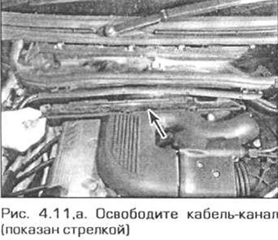
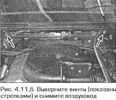
11. At the rear of the engine compartment, remove the air duct for the ventilation and heating system of the passenger compartment. To do this, follow these steps: (fig. 4.11, a, b).
- a) Remove the cabin filter cover by turning its latches 90° counterclockwise. Pull the filter out of the housing.
- b) Unfasten the four fasteners of the cable management box and remove the sleeves with wires from the box.
- c) Remove the four screws and pull the cabin filter housing forward.
- d) In the left rear corner of the engine compartment, pull off the seal, turn the two fasteners counterclockwise and move the trim panel forward slightly.
- d) Remove the two screws and remove the air duct.
12. On the 4-cylinder engine model, loosen the power steering pump pulley bolt and remove the accessory drive belt (see chapter 1).
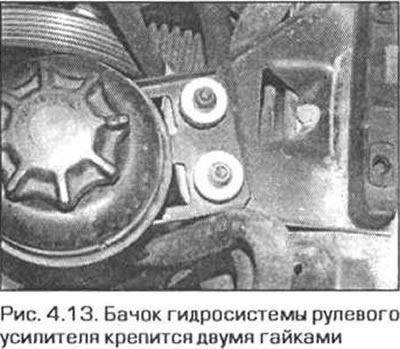
13. Loosen the nuts securing the power steering fluid reserve tank and move the tank to the side without disconnecting the hoses from it (Fig. 4.13).
14. Remove the air conditioning compressor from the engine, release its pipes and move the compressor to the side out of the work area, securing it carefully.
Warning! Do not disconnect the air conditioning system pipes - precautions on this matter are given in chapter 3.
15. Remove the power steering pump as described in chapter 10. Without disconnecting the pipes, move it to the side. If necessary, disconnect the hose going to the rack housing from the mount to the steering gear support.
16. Disconnect the ground busbars from the engine support brackets.
17. Remove the intake manifold from the engine (see chapter 4A).
18. On the N42 4-cylinder engine, disconnect the hose from the secondary air injection valve on the right side of the cylinder head. Loosen the valve mounting nuts and remove it from the engine.
19. On all engines, disconnect the vacuum hoses and coolant hoses. Note their routing.
20. In the safety chains when removing the engine, remove the oil dipstick tube. Remove the sealing ring from the tube. When installing the tube in place, the ring must be replaced.
21. Disconnect all electrical connectors related to the engine. Note the wiring and connector positions.
22. Release the engine wiring harness by unbolting the brackets and sliding it away from the engine. On the N42 4-cylinder engine, it may be necessary to remove the alternator to remove the wiring harness from the engine.
23. Check that all wires have been removed from the engine and that they will not interfere with its removal.
24. Check that there are no hoses or pipes attached to the engine that could interfere with its removal.
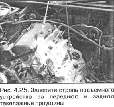
25. Reposition the lifting device, positioning it over the engine. Attach the lifting slings to both engine lifting eyes, front and rear (Fig. 4.25). Tighten the lifting device to remove the weight of the engine from the mounts.
26. Remove the nuts securing the right and left engine mounts to the rubber blocks. Remove the bolts securing the support brackets to the cylinder block and remove the brackets from the engine. On the 4-cylinder N42 engine, we were unable to access the bolts securing the right bracket. Therefore, we left the bracket on the engine and instead disconnected the bracket from the rubber block. The left bracket was accessible and we removed it as described above.
27. Remove the engine from the engine compartment using a hoist. When doing this, hold the engine and turn it as needed to avoid damaging the surrounding body parts and to avoid catching anything important in the engine compartment.
28 The engine is installed in the reverse order of removal, taking into account the following notes.
- a) Tighten all fasteners to the required torque, if specified Technical data.
- b) Lay all the wires in the same way as they were before disassembly.
- c) Install the accessory drive belt in place.
- d) Install the intake manifold as shown in chapter 4A.
- e) Install the radiator (see chapter 3).
- e) Install the gearbox (or transmission) and connect it to the engine (see chapter 7A or 7B).
- g) Finally, fill the engine cooling system and lubrication system (see chapter 1).